


Hello everyone,
I'm facing difficulties getting the UC1625 Brushless DC Motor Controller to work properly.
I’m using it with a 4-Pole motor with 3 Hall-effect sensors. I’m expecting to get a sweet PWM frequency feedback of “12 times the number of rotations per minute divided by 60” and I do get this using a dynamometric hysteresis brake (Magtrol HD-700-7NA). But with some chips, when the motor is put in the final system it works well in a way but not in the other (counter-clockwise / clockwise) ;(
I’ve done some measurement with an Amp Clamp on one phase and a probe connected to the speed feedback frequency and I hope sharing this with you may get me out of the fog.
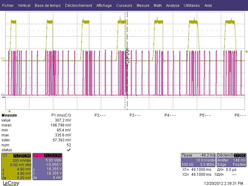
On the first picture, using the Magtrol brake, we clearly see the commutation pattern. More brake leads to higher current but that’s it.

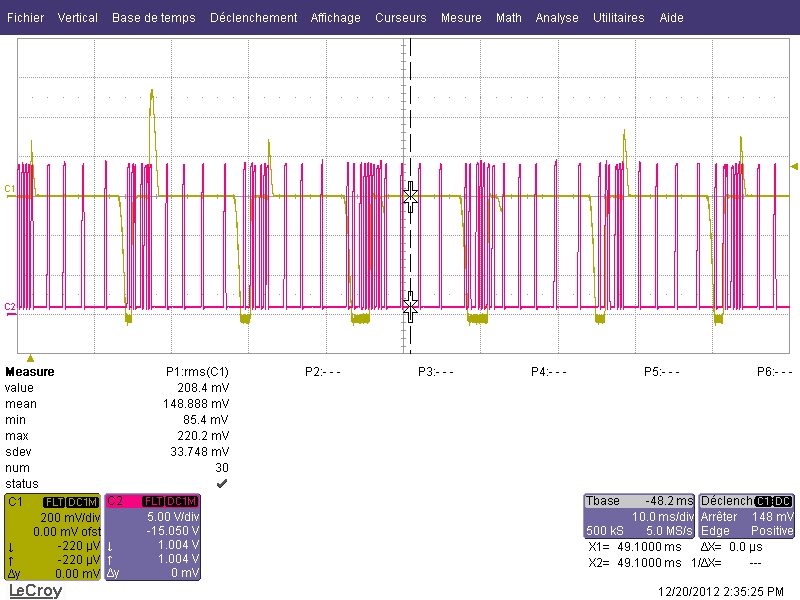
On the second picture, using the complete system with minimum load counter-clockwise, we don’t see anymore the commutation pattern. I think that’s because the brake force applied is not smooth enough. So that sometimes the enslavement causes no commutation and suddenly max current pulse. But it should not be a problem should it?

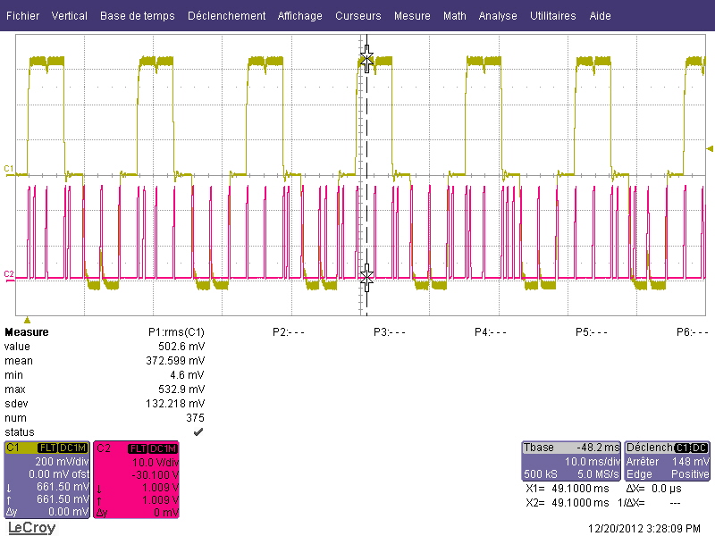
On the next pictures, using the complete system, 1/2 of theoric max-load, you can see the chaotic speed frequency feedback a get (no problem with the same load in the other rotation way).
The polarity of current seems to be less random than in normal operation. For exemple :

I checked the Hall-effect signals, they seem OK and the rotation speed seems OK too. So it should be a problem with the chip generating PWM while managing quite chaotic commutations.
Furthermore, I manage to reproduce the fault with high enough brake using the Magtrol (still only in one way).
If anyone can bring something to help, I will be very pleased :)!
Have a great day.
Thomas.
