This thread has been locked.

If you have a related question, please click the "Ask a related question" button in the top right corner. The newly created question will be automatically linked to this question.

TPS65150: VGH output abnormal

Part Number: TPS65150

   Our color TFT display abnormal sometimes. We found the VGH has no output at that time.  The abnormal display occured when we turn off the ignation and turn it on again within 10 seconds.  The VGH output right and the TFT display normal if the “off to on” time exceed 10 seconds. 

    I need your help. Thank you very much!

  • Hello user5185699,

    Please send a scope plot of the normal and abnormal VGH. Normally if VGH is too low, the device should shut down totally after some time. When you are taking these plots, please plot as well the input voltage close to the input and PGND pins.

    "turn off the ignation" means that you are turning off and on the car, is this correct?

    Best regards,
    Brigitte
  • Hi Brigitte,

    Thank you for your replay.

    The answer is Yes for you questioned at the end of your reply.

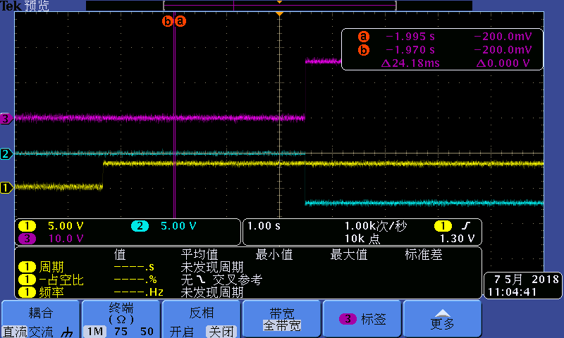
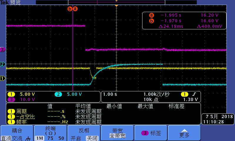
    I have got some plots to show.

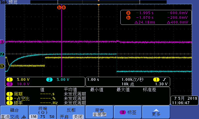
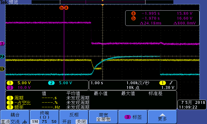
    The purple line is VGH, the yellow one is VIN, and the iceblue one is VGL.  Other plots are the same. The first plot is normal situation.

    The second、third 、fourth plots is abnormal situation,  The differences is the switch time from ignation off to on.

    Do you think is the speed of VGL discharge cause the problem?I'll try later.

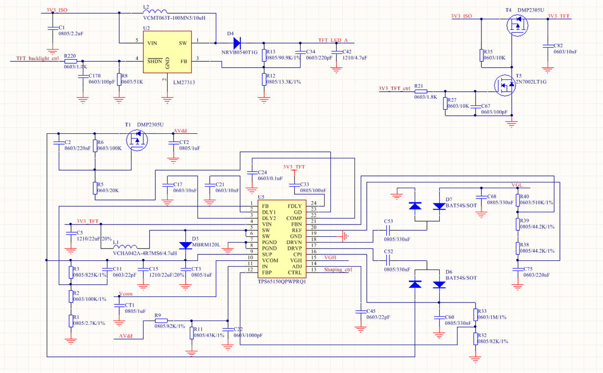
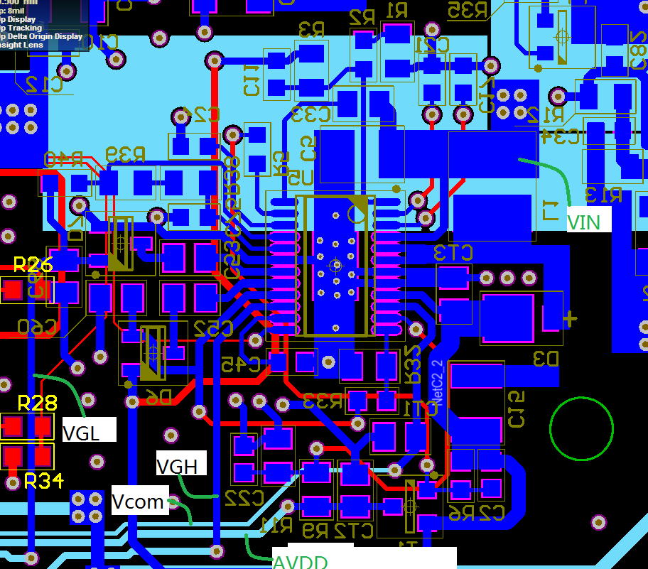
    This is the PCB layout of the design. Please confirm whether it's ok or not.

    I'll tell you the discharge test result a moment later.

    Thank you for your consideration and I will be looking forward to your reply.

    Best regards,
    Yang

  • Hello Yang,

    Thank you very much for the scope plots. Could you please check as well CPI and CTRL? As you have a capacitor connected to FDLY, the part has to shut down after roughly 2.5ms to 6.5ms, which seems not to be the case according to VGL. I wonder if there is an issue with the CTRL signal which turns on the VGH output.

    Best regards,
    Brigitte
  • Hi Brigitte,

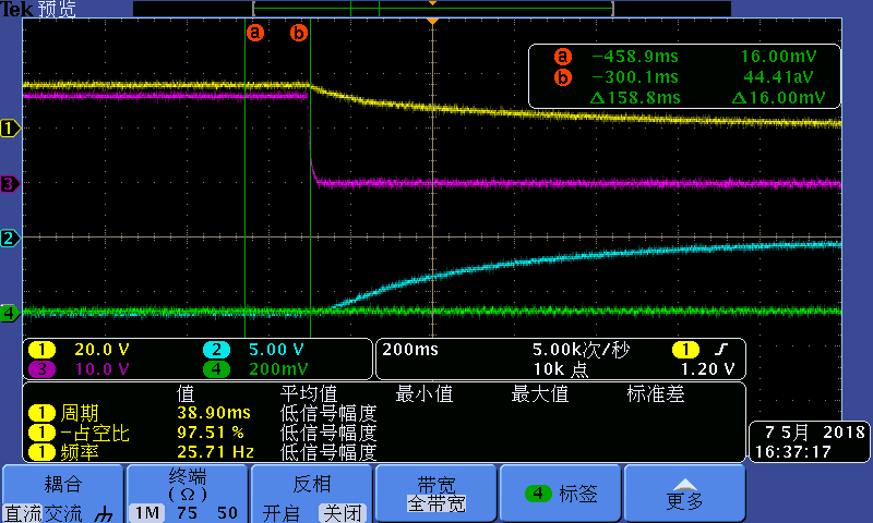
    I got the CPI plot when turn off the ignation. But I can't get the CTRL signal plot. The VGH can't output when connected oscillograph probe  no matter how much time between ignation off and on.

    The yellow line is CPI, the purple one is VGH and the iceblue line is VGL. 

    I connected the CTRL port to I/O of MCU directly. I still cann't understand the function of the CTRL port. Just as a reserved function connect to MCU. Is that ok? 

    Best regards,

    Yang

  • Hello Yang,

    Only if CTLR is high, VGH will be connected to CPI. Could you plese trigger on a rising edge on CPI and make the same plot as you did above? CTRL is a high impedance input.

    Best regards,
    Brigitte
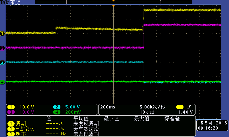
  • Hi Brigitte,

    The plot below is the rising edge on CPI. Should I pull up the CTRL signal after VIN turns on and set a pull down resistor to ensure low level after power off.

  • Hello Yang,

    The CTRL signal needs to be high, when the CPI signal needs to be applied to VGH. If the microcontroller connected to CTRL does not deliver a high signal, VGH will stay low. What is the shaping_ctrl signal doing?
    If you do not need the gate voltage shaping function, I recommend to connect CTRL to VIN.

    Best regards,
    Brigitte
  • Hi,Brigitte

    Thank you very much.  The problem resolved after our SW engineer set the CTRL signal to high.

    I still have some question:

    1. We only set the CTRL signal to high after VIN on.  But it still work correct even if we doesn't set the signal to low after power off.

    2. What's the range of the frequency of the CTRL signal when we use the shaping control function?