This thread has been locked.

If you have a related question, please click the "Ask a related question" button in the top right corner. The newly created question will be automatically linked to this question.

TPS65131: negative output voltage abnormal

Part Number: TPS65131
Other Parts Discussed in Thread: OPA1679

In <e2e.ti.com/.../692786 Brigitte wrote:

> Yes, with the next datasheet update we should include this.

So, how do we calculate the best value for R6?  In addition, although you and the datasheet say `noise decoupling', isn't the most important subject there to compensate the closed loop response with those components?  Moreover, I doubt that there might be no appropriate values of C9 and R6 because:


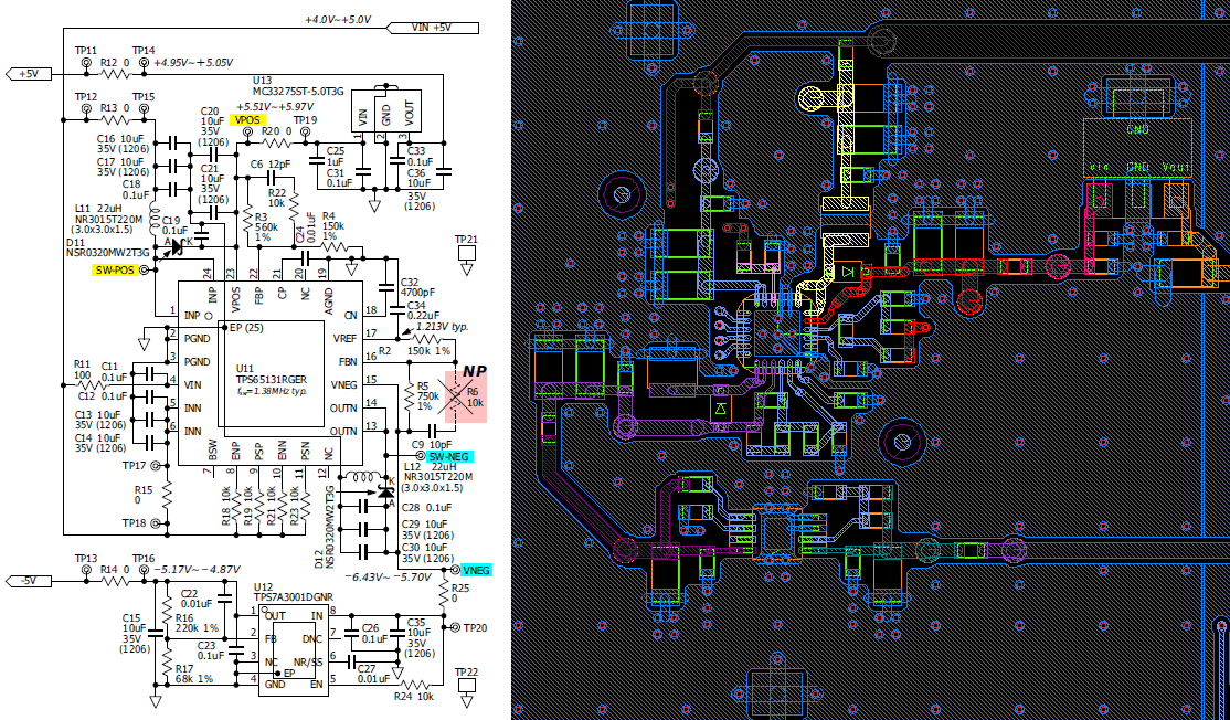
Here are the schematic and the PCB layout extracted from our recent product.  The best R6 value that makes this block give a good stability is infinity, i.e., open.

The loads, mainly three OPA1679 s, consume approx. +/-25mA from the +/-5V output.  Because of such light loads, we use a largish inductance for the inductors in order to reduce(POS) or to avoid(NEG) the pulse-skipping (in other words, to reduce the output ripples).

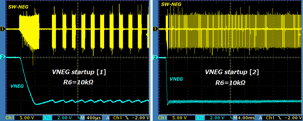
The following picture shows how the VNEG output starts.  Note that the output gets settled approx. 27ms after the start.
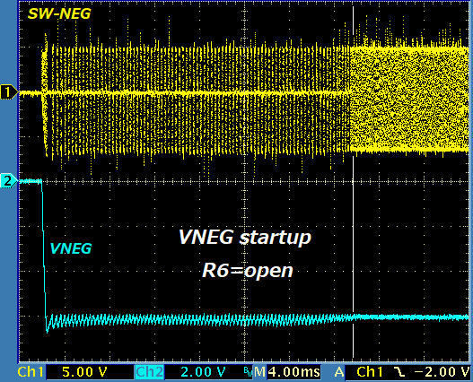
However, if R6=10k-ohm, the output does never seem to be settled as follows:

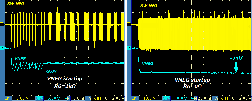
I believe the cause of the oscillation is the unstable closed loop, not the pulse-skipping (being due to the light load).  Furthermore, the smaller value for R6 increases the unstableness as follows.

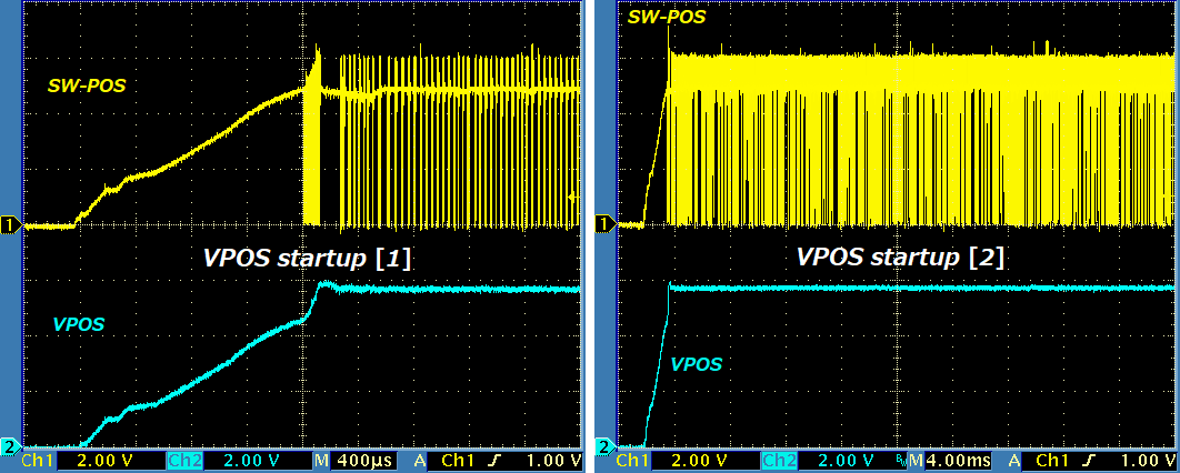
On the other hand, the VPOS output is good enough.  The pulse-skipping occurs as expected but it does not cause the output ripple.
Thanks.

  • Hello Katsumi,
    I will review this and previous post that you had with Brigitte and possibly set something up on the bench to better understand the issue and will get back to you by early next week.
    Kind Regards,
    Liaqat
  • Hello Katsumi,

    Thank you for your patience. I tried to duplicate the high ripple on VNEG that you are seeing at light load. In my lab bench setup using the TI EVM, I  was not able to re-produce it so it does have some board layout dependency as Brigitte mentioned. I also went through previous communications with another customer that had a similar issue and the root cause in that case was noise coupling into FBN pin. With the resistor in series with the feedforward capacitor (C9), that customer's high ripple on VNEG was resolved. You are correct that higher values of this series resistor will provide better results because noise coupling will be lower. There is not a formula to calculate this resistor and and its value will need to empirically determined to see at what point noise coupling into the FBN has been reduced enough to provide lower output ripple. Another factor contributing to un-stable switching in your case could be higher value of indcutor. Does the same behavior happen if you use 4.7uH inductor as recommended in the application circuits?

    Kind Regards,

    Liaqat

  • Hi Liaqat,

    Thank you for a good advice.  The problem has probably been resolved.

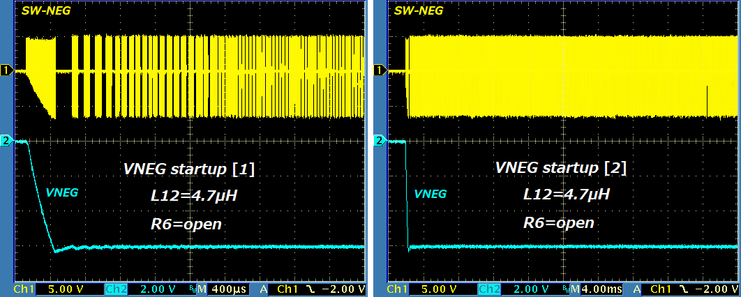
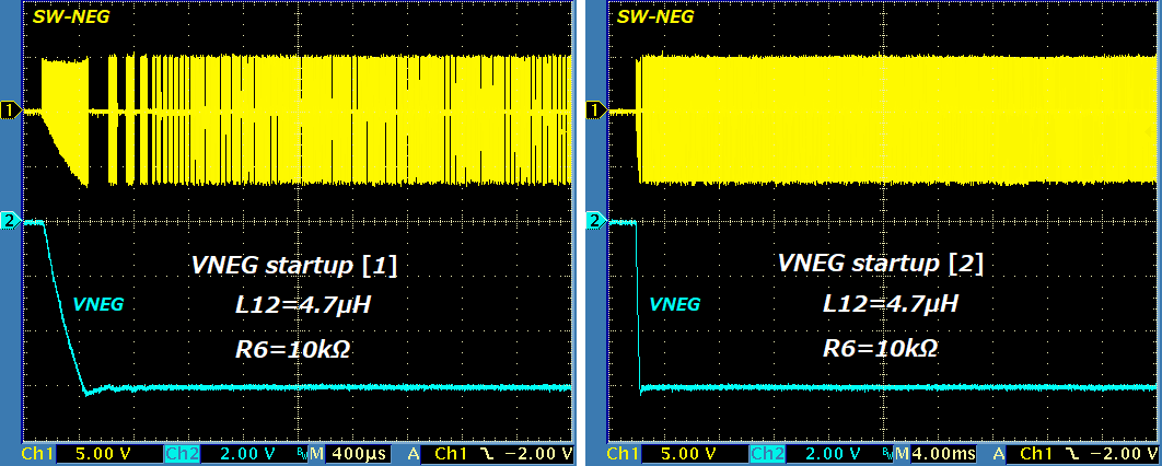
    I tried replacing the inductor L12 22uH with 4.7uH, and verified that the NEG section got stable.  Both the cases R6=open and R6=10k-ohm are ok as follows:

    A pulse skipping got to happen but it seems to never cause a high output ripple.  So, I guess IC's internal has been optimized to work with 4.7uH as for at least the NEG section.  Maybe we should use 4.7uH no matter what load current is.

    Thanks again.

    Regards,