This thread has been locked.

If you have a related question, please click the "Ask a related question" button in the top right corner. The newly created question will be automatically linked to this question.

LM3410: Why does it does not work with this components ?

Part Number: LM3410

Hello,

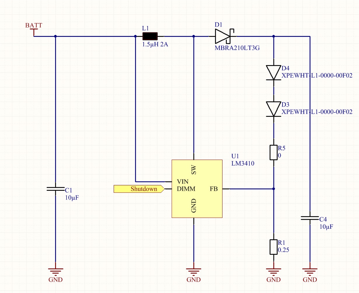
I build a boost driver using the typical boost application circuit from page 1 of the datasheet.

Given these inputs : 

input voltage from 2.7V to 4.2V

output current : 750 mA at around 6.6 volts ( led in series)

Leds twice  XPEWHT-L1-0000-00F02 (datasheet)

Using the datasheet equations, I selected the following components :

Inductor : 1.5µH 3.3A  SRN4018TA-1R5M (datasheet)

Schottky : 0.3v 2A (datasheet)

Output capacitor  2x 1µF 25v ( GRM188R61E105KA12) ( datasheet ), Originally, I planned to use 10µF 25v (C1206X106J3RAUTO) (datasheet)

but for some reason, I was unable to.

Input capacitor : 10µF 10V vJ0805G106KXQTBC  (datasheet)

Rfb = 0.25R 1/4W

I did the following layout :

With this setup, the system is not working. I tried several input voltage, the current is not constant.

Now, I suspect the IC to have passed away: My power supply states 600 mA of current while the current 

thru the led is around 100µA....

What did I do wrong?

Best regards.

Julien

  • Hello Julien,

    It's hard to say from that information, and I can't see the complete layout. But I can tell the layout isn't perfect. I could see some overshoot possibility on startup maybe? Maybe a 10V diode is not rated high enough if there is an overshoot?

    Have you verified all components are populated correctly? Does your power supply have a current limit that is too low (you should have at least a 3A supply to account for current limit)?

    Check the diode to see if it is shorted (if it isn't the input supply limiting) and if so replace it with a 20V and replace the IC because it would likely be damaged if the diode is.

    If none of this let me know and we can get more info.

    Regards,

    Clint

  • Hello Clint,

    Thanks for your time.
    I removed the diode and measure it with a tester. I have the same result than with a brand new one.
    Population : ok.
    Current limit on power supply: ok

    Some more info about the layout:
    - board is a 4 layers. The power plane is divided in 2 parts. The one that is on top of the drawing is the power supply.
    - There's also a gnd everywhere where possible on bottom layer, stitched to inner gnd plane.

    I need to buy some new components... ;) If you have any suggestion that I can add to cart for testing.
    I will order within the next 6 hours... :D

    Regards
    Julien
  • Don't answer this message now, I will bring some more info within one hour.
  • Ok, it's better this morning, maybe for an obscure reason I reached the thermal shutdown.

    Anyway, this is the voltage beetween the schotkky and the first led:

    Then, I switched the 1.5µH inductance to a 4.7µH SRN4018TA-1R5M ( datasheet ).

    It looks (imho...) better (graph at Vin  =3.7v) :

    So my first question is can you explain me why?

    My second question is : The led current seems to be pretty stable from 3.3 to 4.2 V but my goal is to acheive

    a constant current from 2.7 to 4.2v. What should I change?

    Thanks

    Julien

  • Hello Julien,

    I could tell a lot more from the SW waveform and also the inductor current if possible. But from what it looks like the 1.5uH has too high of a current ripple and it may be saturating the inductor and/or hitting current limit. This would explain why the 4.7uH helps.

    The likely reason you cannot get regulation down to 2.7V input is also likely due to inductor saturation. The 4.7uH has a saturation rating of 2A. With current ripple you are likely close to or exceeding that when you lower the input voltage. That will cause current limit as well if it saturates. I would try a 4.7uH inductor with a saturation current rating 3A or higher and see if you can run at the lower input voltages.

    Regards,

    Clint

  • Hello Clint,

    Based on the same design, I populated a new board with brand new components.

    I changed schotky to 45V 5A (datasheet).

    Inductance to SRN6045TA-4R7M 4.7µH 4.5A (datasheet)

    According to my calculations (2.7 to 4.2v boosted to 6.6v, out current = 0.76A) :

    - Duty cycle is from 0.65 (Vin = 2.7v) to 0.46 (Vin = 4.2v)

    - Delta IL : 0.12 to 0.13A

    - I Peak = 2.3 to 1.53A

    Contrary to my previous tests ( I did not measure it before this post ), output current is now ok when Vin is above 3.3v 

    but below 3.3v, output current can not be maintained.

    To me, passives seem to meet the requirements.

    Any idea ? can it be a layout issue ?

    Regards

    Julien

  • Hello Julien,

    It could be a layout issue and I can take a look at it if you like, but it really just looks like you are pushing the limits of the device. The current limit can be as low as 2.1A and given the tolerances of the inductor you could easily be exceeding that at lower input voltages. That would be easy to check, just reduce the output current to something like 650mA and see if you can go to a lower input voltage.

    Regards,

    Clint