This thread has been locked.

If you have a related question, please click the "Ask a related question" button in the top right corner. The newly created question will be automatically linked to this question.

TLC5944 ghosting problem

Other Parts Discussed in Thread: TLC5944

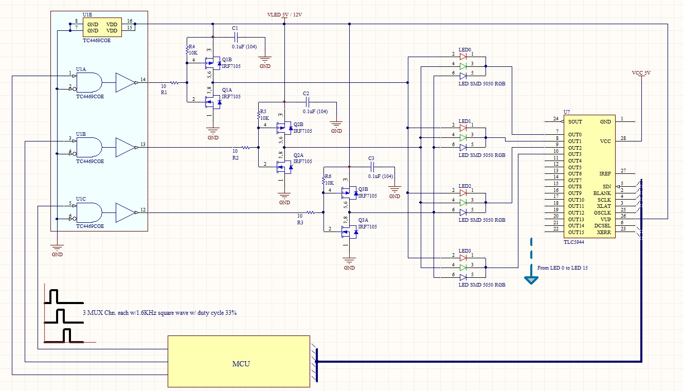
I´m using a TLC5944 for a project where I want drive 16 RGB LEDs but I have a problem with ghosting.

Each LED cathode are directly connected to the TLC outputs.

To drive each column of anodes (RGB) I tried two solutions:

The first was with a TC4469 and all works fine but this driver only can deliver 250ma and is not sufficient when I want turn on all 16 LEDs at the same time.

My second choice was try a "totem pole" configuration as I saw on the datasheet, everything seemed to be fine and all 16 LEDs turn on at same time, but the ghosting problems began here when I saw the red emitter with a little glow.

The problem is present with a VLed = 5V and if Vled = 12V also the green emitter show the same problem.

I tried with two different models of MOSFET to build the "totem pole" high-side (IRF7105, IRLML6402 and complementary) and the problem is the same. I tried changing the Rgate for reduce ringing and the problem is minor but all leds are dimmed.

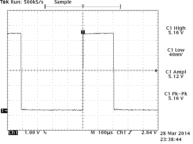
For multiplexing I'm working with a low frequency (1.63KHz) and each duty cycle for RGB is 1/3 from 1.63KHz.

How I say before, if I use TC4469 the ghosting problems disappear. I can't understand what is wrong with my totem pole.

Several days ago I'm trying to solve this problem but I can't.

Could somebody help me please? May be a suggestion or send me a schematic for build the right driver, please

Thank you

Julio

  • Hello Julio,

    Sorry for late reply.
    For "totem pole" configuration, do you mean the schematic on page24 of datasheet?
    If yes, what's gate signal of low-side N FET? Shorted with the gate of high-side P FET?

    What's the BLANK signal when you switch power supply from one line to next? BLANK should be high before you switch off the power supply of current line. Then switch on power supply for next line, then wait some time, say, 1uS, then put low BLANK and begin input GSCLK.
    what's the connection of VUP pin?

    It's better to understand your problem if you can share your schematic and some measured waveform of TLC5944 outputs pins.

    Best regards

    Mike

  • Hello Mike

    Thank you for answer my question.

    I send you the schematic from my circuit in attached file.

    All signals controls are ok and I'm dealing with this problem yet.

    I have made a lot of hardware test and the only approach to fix the problem is changing the Vf from the red LED but this is not possible on the real world because all kind of RGB LEDs come with a VF for red emitter that is smaller than VF for blue or green emitters. If I place a green o blue emitter instead red, all works fine.

    I don't know how can I solve this problem, I'm in lighting business and this project is for commercial use.

    I don't want use 3 x TLC5944 because PCB size and cost not match with the kind of user for my fixture.

    Could you help me please?

    Kind regards


    Julio

    PS: Could you change my main email address to jkalizsky@showdeluces.com, please.

  • Hello Julio,

    I assume your timing diagram as below.

    If yes, could you help measure the waveform for me?

    Also please confirm if any other bulk capacitor for each line (A/B/C as marked in below picture)?

    Thank you

    Mike

  • Please click the picture to get a clear look, thanks

  • Hi Mike,

    I've tried with all kind of values for capacitors, resistors, diodes, etc.


    The datasheet from TLC not show any specific value for the Vf of LEDs, I'm trying to use chinese RGB LEDs like 5050 used in strip leds, are very cheap and very easy to find. Others LED from specific brands raises the price for my project.

    Regarding your question about the the red emitter, when VLED = 5V only the red emitter show a problem, but when VLED=16V all emitters (RGB) have a ghosting effect, except if you connect four LEDs arranged in serie and only the red have ghosting.

    Below I send you the information requested:

    Thank you very much

    Kind regards

    Julio

    GATE INPUT:

    TOTEM POLE OUTPUT

  • Hi Julio,

    Thanks for your waveform. Could you please check my below question?

    Thank you

    Mike

  • Hi Mike

    I hope the following images answers your questions:

    Gate Input


    Outputs & Blank


    Output Red + Blank

    Output Green + Blank

    Output Blue + Blank

    Thank you very much for your help


    Kind regards

    Julio

  • Hi Julio,

    Please measure below waveform with OUT0(pin 7 of 5944) added:

    Thank you

    Mike

  • Hi Mike

    Please find below the answers to your questions:

    The following measurement was made with all LEDs set at GS = 0 and DC = 63

    Out A (Red) + Blank + Pin 7 (Out 0)

    Out B (Green) + Blank + Pin 7 (Out 0)

    Out C (Blue) + Blank + Pin 7 (Out 0)

    Thank You

    Julio

  • Hi Mike

    Have you received my last email?

    Do you have any news regarding this issue?


    Kind regards


    Julio

  • Julio,

    Sorry late reply.

    I checked your waveform, but can't see any chance that Red LED will be turn on, see below:

    You mean you can see red LED connected with pin7 have some dim light under this condition?

    Thank you

    Mike

  • I can't understand 100% what you mean but I can tell you we are working with two completely different protoboards and both have the same problem and the only solution found was when replace the red emitter by another green or blue, that mean emitters with same Vf don't showing ghosting but you know any RGB have emitter with different Vf.

    We work with different cable lenght, different MOSFET drivers and also we change lines of code.
    In attached file you could see the ghosting effect.

    RGB LED 5 mm.

    RGB LED 5050


    This represent a serious problem, because two peoples are working and trating to solve the problem and can't found any solution yet.

    I hope you could help me because we need to finish this proyect ASAP.

    If you want I can send you via private email my schematic and code. Just tell me if you want, if you are agree please send me the petition via private email account.

    Kind regards

    Julio

  • Hi Mike

    The drop mentioned by you, observe the others waveforms only happen with red, the waveform for green and blue not show the same effect.

    Julio

  • Hi Julio,

    I still can't understand why red LED have ghost. I can see your picture, when let green or blue LED turn on, the red LED also have dim light. How about if all three color LEDs turn off(GS=0), will red LED still have ghost?

    Although I do not think the drop waveform of pin7 due to line switch is the root cause of red ghost, but we may remove this possibility by inserting a deadtime between line switching, see below picture:

    If it still doesn't work, can you increase VUP a little higher than VLED? say, 5.5V VUP?

    Thank you

    Mike

  • The news are the following:

    With VLED = VUP = 5.12V we have the ghosting problem

    With 3 LEDs and VLED = 5.12V and VUP = 6.5V the problem was fixed but with 16 LEDs reappears the problem.

    With 16 LEDs and VLED = 5.12V and VUP = 8.38V the problem was fixed again.

    ¿What do you think about this, the datasheet don't tell nothing about it?

    Can I set a VUP with a voltage so far from VLED?

    Do you have a technical paper about this?

    Kind regards

    Julio

    VLED = VUP = 5.12V

    VLED = 5.12V and VUP = 8.38V

    RED OFF

    OUT0 (ch1) + BLANK (ch2) + OUT MOSFET RED (ch3)

    RED AT MINIMUM BRIGHTNESS

    OUT0 (ch1) + BLANK (ch2) + OUT MOSFET RED (ch3)

    RED AT FULL BIGHTNESS

    OUT0 (ch1) + BLANK (ch2) + OUT MOSFET RED (ch3)

  • Hello Julio,

    Usually we suggest short VUP and VLED. Theoretically, this should be able to solve ghost issue.
    Maximum voltage rating for VUP is 15V, that means you can always short VUP and VLED, as long as VLED less than 15V(sometimes, you need drive several pcs LEDs in series, then you may need higher VLED).

    Use a higher VUP than VLED will cause one drawback: The higher VUP voltage will apply on the LEDs(some LEDs anode are pull low to ground, while its cathode is connected to OUTx which are VUP voltage). In other words, the LED will have a higher reverse voltage accross, this may shorten the life time of LED. That's why we didn't suggest different VUP/VLED on datasheet.
    In your case, you need check if the LED can sustain 8.38V reverse voltage.

    From your input "With 3 LEDs and VLED = 5.12V and VUP = 6.5V the problem was fixed but with 16 LEDs reappears the problem", I strongly suspect this problem may related with layout. Could you enhance the ground connection between IC and MOSFET? I didn't see any cap for 5944, do you have it? It's better to have a ceramic 1uF beside VCC and GND pin.
    Do you also have ceramic bulk cap, say, 10uF, for VLED?

    Do you mean that no improvement after adding 1uS deadtime as I suggested in previous post? do you have waveform?

    Regards
    Mike

  • Hi Mike

    Finally the solution was add a deadtime like you suggest, with 125ns was sufficient.
    Was necessary modify the code but I don't have more ghosting.

    See image for reference:

    Kind regards and thank you very much for your kindness.

    Julio

    PS: I need know if you or any other assistant can change my main email address used for login in your site. How can I do this update?

  • Hello, Julio,

    Great to heard that issue was solved!

    I don't know how to change the login email address, and I'll forward your request to other people for help.

    Best regards

    Mike