This thread has been locked.

If you have a related question, please click the "Ask a related question" button in the top right corner. The newly created question will be automatically linked to this question.

TPS7A33 and TPS7A47 Output Issues

Other Parts Discussed in Thread: TPS7A33, TPS7A47

Hi All.

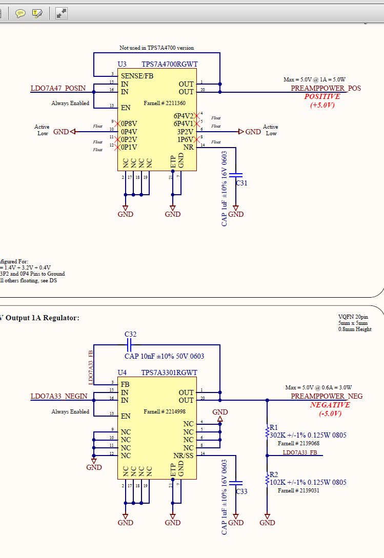
We are using the TPS7A33 in a VQFN package as per figure 28 in the TPS7A33 data sheet. All pins buzz out correctly, no erroneous shorts to ground.

Vin is -6.53V and En is tied to Vin so also -6.53V. The soldering seems fine, and a stencil was used for solder paste. The bare PCB is also correct as per the schematic. 

However, the TPS7A33 just sits at 0V or something small like 0.1V. I wouldn't have thought it was a bad device as this has happened to both TPS7A33 and TPS7A47 regulators on the PCB and with 2 populated PCBs.

Any help would be much appreciated.

Thanks.

Ed

  • Hi Ed,
    Would you be able to post the schematic and layout that you are using for the LDO's? Also just want to make sure that I am interpreting this correctly that on both of your PCB's both the TPS7A33 and TPS7A47 are not working?
    Best Regards,Mark
  • Thanks, yes that is right, we have tested 2 populated PCBs so far, both failing. The PCB design contains both the TPS7A33 and TPS7A47 as we are generating regulated +/-5V rails for a set of pre-amplifier modules. 

    The schematic is here:

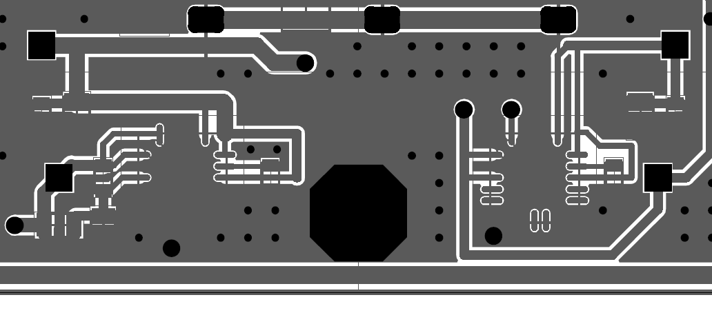
    The layout (bottom layer with IC also on bottom layer) is here:

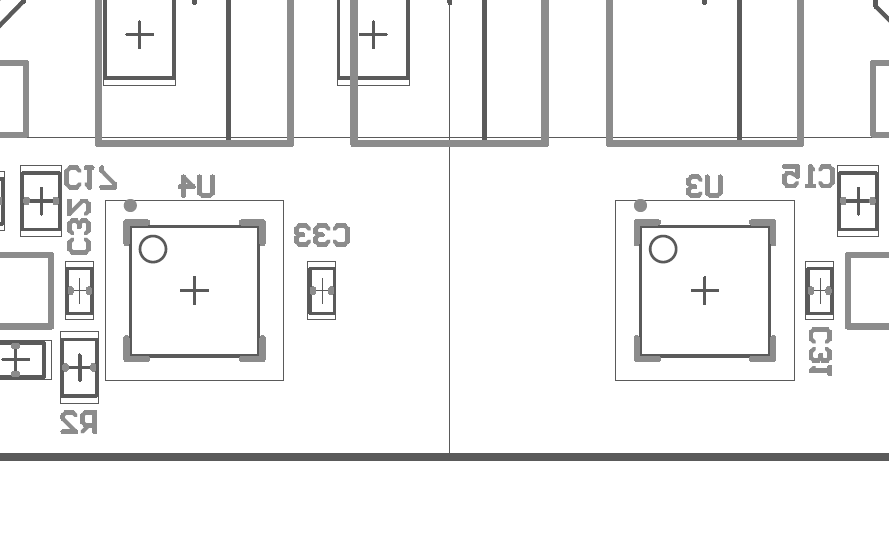
    The IC identifiers are here:

    I've tested shorts to ground on U4 (TPS7A33) (seeing as the output is sat at 0V) giving:

    Pin 1 = Open - Correct

    Pin 2 = Closed

    Pin 3 = Open

    Pin 4 = Closed

    Pin 5, 6, 7, 8, 9, 10 = Closed

    Pin 11, 12 = Closed

    Pin 13, 14, 15, 16 = Open

    Pin 17, 18, 19 = Closed

    Pin 20 = Open

    Many thanks in advance...

    Ed

  • Hi Ed,

    Would you be able to post a scope shot of the outputs and inputs of both regulators?

    Thanks in advance.

    Best Regards,

    Mark

  • Hi Mark.

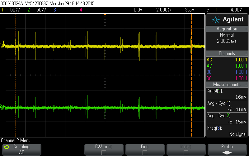
    I've checked for any short between input and output via the feedback loop, no short. Below is a scope probe waveform for both Vin at -6.5V and Vout at 0Vdc. The scope was set to AC coupling. 

    As we can see there seems to be a direct coupling from input to output, other than the DC value, suggesting some kind of capacitive coupling.

    Thanks

  • Hi Ed,

    If you look in section 10.1.1 of the TPS7A33 datasheet you can see that in order to improve noise and reduce coupling between the input and output caps that the ground of the output capacitor should be connected directly to the ground pin of the device. It should not be connected to the ground plane of the board as that can cause coupling between the input and output.

    Also, when looking at your layout and IC identifiers I was unable to tell which direction you are looking that the board from. For the picture with the IC identifiers it appears that you are looking at the bottom plane of the board by looking through the top plane due to the way all of the identifiers are backwards. If that is true then you should check to see if the way it is layed out corresponds with the pins that are on the device and that it is not backwards.

    Best Regards,

    Mark

  • Hi,

    I have the same problem with tps7a33 output. The output is always about 100mV. Did you find out what was the problem, Ed?

  • Hi, 

    I'm afraid I can't remember directly as this was a while ago, however any comment I give is caveated by our board having an incorrect footprint. 

    We had two main issues, one was shorting when the solder paste was uses. This was a product of a landing pattern too finely pitched for the population process we used. The other issue was capacitive coupling due to a) some incorrectly chosen caps and b) the placement of those caps with respect to other components. 

    For the most part getting it running was a board re-spin and a fresh pair of eyes into the population process. 

    Thanks.