This thread has been locked.

If you have a related question, please click the "Ask a related question" button in the top right corner. The newly created question will be automatically linked to this question.

TPS544B20 won't source current properly

Other Parts Discussed in Thread: TPS544B20, TPS544C20, LMZ10500

Hi,

I was testing a TPS544B20 on my board. In my application VIN = 5V and VOUT = 1.0V. The regulator was working fine at one point but there must have been some type of electrical overstress that caused the regulator to function properly.

I did run some load transient testing on this part. The transient testing was tested in two parts (0-4A) and (4-8A). I set my electronic load to cycle these tests at around 500 Hz.

I then ran some more testing on some other supplies including the 5V that feeds the VIN of this suspect part. There were some problems that did cause some other supplies to be damaged. I was able to fix these problems but I am still not able to get the 1.0V part to work properly.

Symptoms:

1. When I connect an electronic load (EL) to the 1.0V supply and set the EL constant current mode (CC) and try and get 1A out of the 1.0V regulator it won't source that much current. The most I have measured is around 260mA.

2. The Fusion tools report that everything looks good. No faults are present. The Vout is at 1.0V but the current shown is about 250mA.

I probed the COMP, SW and BOOT pins and so far it looks fine except for the switching frequency and ON times don't make sense to me. I need some help in figuring this out. I did take a few scope shots that I can upload.

I also probed the TPS544B20 EVM from TI. I am trying to do a side by side compare but so far I haven't found anything significant. Once again I'm not sure why the switching frequency that is set my the Rt resistor doesn't match what I see on the scope.

I would think that the ON time would vary depending on the load current but I haven't seen this. What am I missing?

Thanks,

Rudy

  • Hi Rudy - Can you upload some of your waveforms? Most interesting would be the SW, Comp, FB and the inductor current. 

    The TPS544C20 uses an adaptive constant-on-time control scheme (TI calls it DCAP-2), so the ON time should not change much over loading conditions. There may be some slight shift in the switching frequency at heavy load (maybe 10% over full 30A load), but I wouldn't expect there to be too much difference at lighter loads like this. 

  • Matt,

    I have uploaded the pictures from my board as well as some pictures I took of the TPS544B20 eval board.

    Thanks,

    Rudy

    Scope_Shots.zip
  • Hi Matt,

    The board that I am working on has (4) TPS544B20's.
    - The main TPS544B20 regulator provides 5V0 to all the downstream regulators.
    - The (3) remaining TPS544B20's take the input 5V0 and generate 1V2, 1V0 and 1V028. All three of these are not able to source current. The scope shots I sent you were from the 1V0 regulator.
    - I also have (6) LMZ10500 regulators (much lower current rails) that all are fed from the same 5V0.
    - During my testing I must have caused some electrical overstress that caused (2) of the LMZ10500's to be damaged. I was able to fix these problems by removing the bad parts.

    Is it possible that the (3) downstream TPS544B20 controllers were damaged? Can the controller be damaged such that it can't source any significant amount of current but still have a valid output voltage?

    Thanks,

    Rudy

  • Hi Rudy -

    Its possible that the TPS544B20 has been damaged, but I do not see anything out of the ordinary with these plots... One point I'm not clear on: there are two switching frequencies, 250kHz and 600kHz. Do these come from the regulator under different conditions, or before/after stress? 250kHz is the default frequency, TPS544B20 would likely go to 250kHz if, for instance if the RT, or ADDRx pins (they multiplex the same circuit) were stressed. This is unlikely but can happen if one of these pins gets shorted above its abs max. 

    However, the device is still switching, which means it should be able to supply current. What happens when you try to pull say 5A out of the regulator? Does the output or input voltage drop out? What does the inductor current look like? What happens if you try a power resistor 

    If you suspect the device is damaged, it might be easiest to try replacing it instead of debugging. 

  • Matt,

    1) The 250Khz is from the TPS544B20 eval board from TI. The resistor that sets the switching frequency is 38.3Kohms. According to the datasheet the nominal Fsw should be 500Khz.
    2) The 600Khz is from my board. The resistor that sets the switching frequency is 86.6K. According to the datasheet the nominal Fsw should be 750Khz.
    3) I have tried to pull higher currents and Vin and Vout stay steady (does not drop out).
    4) How do you want me to measure inductor current? I currently have a current probe (channel 4 on the scope shots) that is measuring the current from the positive lead of the wire going from the electronic load (EL) to the Vout of the regulator. The EL as has a display that shows the current. Both the scope and the EL report the same current. Did you want me to try and lift the output end of the inductor and place a wire down to the pad and then put a current probe on this wire?
    5) I am getting ready to try a resistive load (1 ohm - 25W 1% resistor). I should be able to draw 1A with this load. I'll let you know what I find in a little while.
    6) I am running out of experiments to try. I do have a spare part that I can use to replace the suspect part.
    7) Does it make sense to try and restore the part to its default parameters using the TI Fusion tools? Is this possible?

    Regards,

    Rudy

  • Hi Rudy - Just a thought: is there any chance the input supply is current limiting? Or maybe just as a sanity check, connect the e-load to your lab supply to see that it is indeed drawing >1A as expected. 

    1,2) This is odd, especially the part about the EVM. The first thing is obviously to check the resistors populated, but the EVM should be OK. In any event, I think this may be a secondary effect, lets not concentrate too much on it now. We could do some further debugging, if needed... Is it just this board at the wrong frequency, or all of them?

    3) The only way the TPS544B20 can limit current is by either truncating its ON-times (short ckt protection), or simply not switching (i.e. shutdown/restart, hiccup). If the device is switching, and both the on-times and frequency remain approximately constant. The inductor current will help us get a cleared picture about whether both FETs are switching complementarily. 

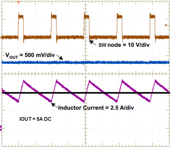
    4.) I'm looking to see the inductor current "triangle" waveform. The inductor current charges linearly when the high-side FET is on, and discharges linearly when the low-side FET is on. To measure this, I recommend lifting one side of the inductor, and placing a wire between it and the output capacitors. Its a best practice to place said wire on the VOUT side of the inductor, to avoid any coupling issues to the probe because of the high dV/dt switching waveform. This will tell us if indeed both FETs are switching, or if there's anything else "funny" going on, like a saturating inductor. 

    5.) This is a good idea. A resistor is just a resistor and will of course follow Ohm's law. If the output remains at the right. As a sanity check, look again at the inductor current. The DC level of the inductor current will represent the DC output current. 

    6.) Swapping the IC may be worth a try if nothing else is working, but I would try the experiments above first. 

    7.) It will not hurt to restore the NVM, but none of the settings should be causing anything like this. The output current limit is a shutdown/restart event, which would be noticeable on the scope... 

  • Matt,

    Regarding item 5 from previous post:
    - I connected a 1ohm 25W +/- 1% resistor to the output as my load.
    - The suspect part is able to source 1A.

    Not sure what is wrong my electronic load. I need to investigate. The setup with the EL is working with the TI TPS544B20 eval board.

    Rudy

  • Matt,

    1) I measured Rrt on the EVM and it is 17.8K. According the datasheet the nominal Fsw should be 300Khz. It looks like the schematic (38.3K) and the actual PCBA (17.8K) do not match. This explains why the Fsw on the EVM is at 250Khz.

    2) I measured Rrt on my board and it is 86.6K. All the Fsw mean values seem to be in the next lower 2 bin values (56.2K and 38.3K). The max values seem to be within tolerance.

    4) I'll try and set this up. Just to be clear you want me to capture the "current triangle" waveform by lifting the Vout side of the inductor and placing a long enough wire where I can insert my current probe. Since this is prior to the large output caps I should be able to see the dV/dt switching waveform. Is this correct?

    5) The large 1 ohm power resistor works! The supply is able to source 1A at Vout = 1V as expected.

    6) I am going to defer this until I get to the bottom of why the power resistor works and the EL does not.

    7) I may try this later on to see if it matters. The device is set to hiccup mode.

    I am going to reset my EL to factory defaults to see if there is an issue. This doesn't make sense because I tested the EL with both my bench supply and the TI EVM and it works in both cases.

    Thanks,

    Rudy

    5)

  • Hi Rudy- Its good to hear that the device is working... 

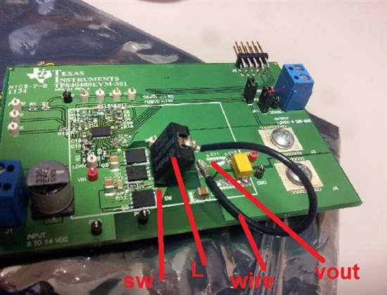
    I've uploaded a picture of a board with an  "inductor loop" i had at my desk, along with an example. The actual board is a buck controller, but its the same principle. The current clamp probe goes around the wire. 

    waveform.

  • Matt,

    I found the problem!

    It looks like I have a bad cable. The hot (red) lead from the EL to the PS was to high of a resistance. The measured value was around 60 ohms. The ground lead (black) is about 0.3 ohms. When I replaced the "hot" lead the EL started working properly again.

    Last Friday when I was doing some testing on one of the (4) TPS544B20 regulators (not sure which) I set the EL to provide a max of around 8 to 12A. I was trying to see how much I could load the supply before the Vout would get out of regulation. I remember that the "Red" lead got very very hot. I'm not sure how long the wire was in this state. These wires rated at 25A.

    Thanks for all your help!!!

    Rudy