This thread has been locked.

If you have a related question, please click the "Ask a related question" button in the top right corner. The newly created question will be automatically linked to this question.

LM3677 - Adding Loads = Current Latchup - No Bueno

Other Parts Discussed in Thread: LM3677

Hey Everyone.

So I just added the LM3677 to our system, which is a very low-power IoT +  energy harvesting system.

I made a dev kit for this design, and I have jumpers to remove-add device power for power tracking, etc. I have reliably seen when I add a small load such as a Cortex-M0 running a mere 3mA, it causes the LM3677 to latch up to 18mA. If I remove the load, it is still stuck, and is constant. If I cycle the power with the additional Cortex-M0 load (adding jumper), the buck is stable. 

I am worried if during a transient of 3mA that is not adding a jumper but rather a BLE Tx/Rx, could cause the latch-up.

Does anyone know what this could be?

Device: LM3677TL-1.82/NOPB

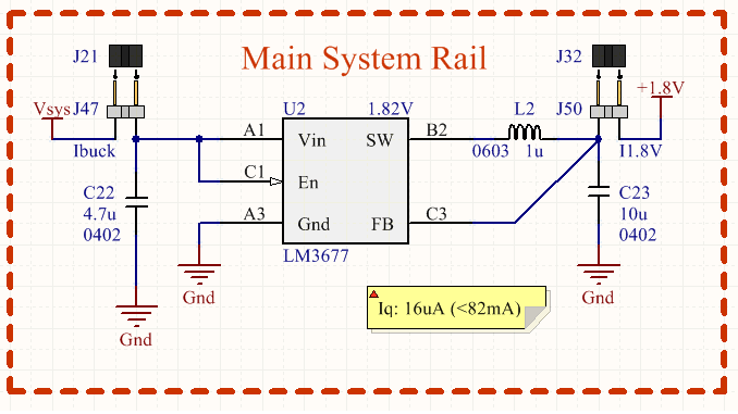
Cap on Vin: 4.7uF (6.3V)

Cap on Vout: 10uF (4v)

Inductor: 1uH, 650mA Max, 20% Tolerance.

The only thing I can think of is there is an issue of the device switching from the PFM <==> PWM modes. But this is dynamically right? Also, I am no where near the 75mA threshold, my total system current is less than 6mA.

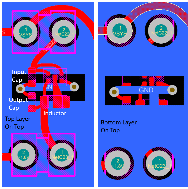
Also my layout is solid, I have a local LM3677 ground plane for current loop, and branch-connect it over to the main ground.  Vout is clean on the scope. 

Please help!

Thanks,

-Peter

  • Hi,
    is the EN pin tied to VIN directly? is the jumper you remove-add at VIN line? if so, this may be the cause, on the datasheet pg13, states
    "The part uses an internal reference voltage of 0.5V. It is recommended to keep the part in shutdown until the
    input voltage exceeds 2.7V."
    so if the EN and VIN ramping together, it may cause the latch-up you seen.
  • Hey Sheng,

    Thanks for your reply. My issue with with the output side. If I have a stable jumper on the input, in which Vin and En are shorted with the power source, and I remove ot ad a jumper on the output side. The jumper adds or removed a 3mA load, the device will go haywire. If I power cycle, the problem is gone. It has to do with the jumper on the output.

    I have even seen where I just add a jumper which has nothing loaded to it. So the jumper just connects the output to my routing network, but all of the other loads are disconnected. See attached picture of schematic of the buck. I have doubled check pinout, layout (ground loops done).

    I am running this guy at the very low-end...max system load is 8mA, with transients in the 30mA(10usec). 

    Only thing I can think of is the debouncing of the jumper when applied or removed causes erratic behavior on the FB pin. 

  • this is strange, do you probe the SW pin, to see if the part jump to/stuck at PWM mode?

  • Sheng Jin,

    I still have this problem. Trying to address it again. I suspect it is what you stated, and it is now biting me in the butt. In all honesty this is my fault but this is pretty bad, this is soo common to do this. My board is the size of a dime or less. I have no signals to drive this signal. My entire system runs on 1.8V, when how do I drive a signal when my system is not even on? Only thing I can think of is to use an RC circuit to give a delay to that pin.

    Have you seen this issue elsewhere?
  • Peter,

    Yes, we had seen other customer had similar issue before. so I guess the best solution for you is to add a simple RC delay at EN pin.

  • Hey Sheng Jin ,

    Thanks for replying so quickly.

    I am also having the same problem on the back end:

    - Load is disconnected from the 1.8V at J50, shown in the schematic above.
    - load is a mere 2mA at 1.8V, static
    - Jumper applied...this also throws the device into this same erratic loop, causing it to draw 15mA.
    - Cycle power using a power supply which has a ramp-up, problem goes away.

    Have you seen this issue? This one doesn't happen all the time, but 90% of the time.

    Does this IC have trouble with it's transitioning from the 2 power modes?
  • Hello Peter, does this load connection represent what the real system will look like?
    When in production, will jumpers be used to connect Vin and Vout?
    May I suggest testing Vin transients with a controllable voltage source.
    And Vout transients with a controllable electronic load.
  • Hey Ed,

    No, that is a electrically equivalent dev kit of our product. Remove jumpers and it is the exact same.

    The loads I am working with currently are just to figure out what is going on.

    My real currents are:

    - 10mA max constant draw

    - 30mA transients @ ~1ms or less

    - 500uA avg. product current.

    That is the dev kit layout. product is similar. I know it's not perfect but I am only using 10% of the product's capabilities, so my loop currents are super low. 

    When connected yo my power supply Sorensen, which has a ~1ms ramp, it works perfectly everytime. But still I'd expect the same issue as my Vin and my EN pins are shorted.