This thread has been locked.

If you have a related question, please click the "Ask a related question" button in the top right corner. The newly created question will be automatically linked to this question.

TPS54625 is not Turning ON with Load/Without Load

Other Parts Discussed in Thread: TPS54625

I have generated the Buck Converter circuit using TPS54625 with 12V Input and 5.4V output in WEBENCH. And the same circuit is used in my design and circuit is shown above.

After giving 12V Input  am Not Measuring 5.4V Output(I Have tried Without Load and With Load)

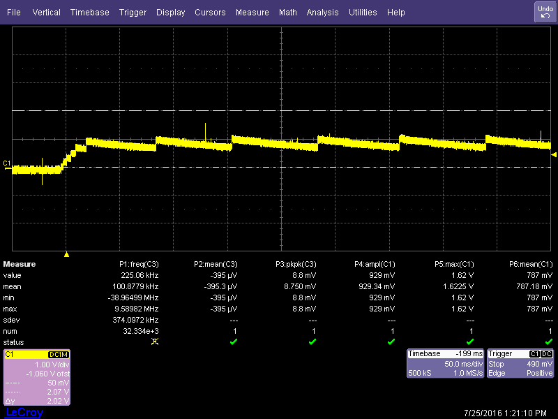
I have captured the Output Using Scope and is shown Below

I have captured the SS Pin Signal Using Scope and is shown Below

I have captured the SW1 and SW2 signal Using Scope and is shown Below

Initial Stage of  SW1 and SW2 signal is Zoomed and is shown Below

Middle portion of  SW1 and SW2 signal is Zoomed and is shown Below and found some irregular switching pattern

 Zoomed the Irregular switching pattern and is shown Below

Zoomed the end of switching patter and shown below. After this the signal slowly reaches to 0V as shown in full capture of SW1 and SW2  signal

What might be the problem here and Do You have any solutions for the Problem ?

Thanks for your help.

  • Your input voltage is rising too slow. TPS54625 is a buck converter. To get 5.4 V output the input voltage must be above about 6.75 V before the end of the SS time. Otherwise TPS54625 will shut down due to UVP after 1.7 x tss.
  • Thank You for your feed back

    As per Circuit the capacitor used in SS Pin is 8.2nF and this corresponds to 1.15mS soft start time(1.15ms*1.7ms=1.995mS).

    As per measured results also Buck converter is turning off Approx around 2ms.

    Considering my 12V input is rising slowly, If I change the SS capacitor to 50nF , The Soft start time will be increased to 7.0125ms(7.0125*1.7=11.92mS). I will get around 9mS more time for my input voltage to reach greater than 6.75V.

    Pls Conform if I Change the SS Capacitor to 50nF,It will help me to solve the issue and also conform due to increasing value of SS Capacitor will any other parameter of Buck Converter gets affected?
  • 7 msec is not too long. I typically recommend between 1 and 10 msec.
  • I have replaced the SS Pin capacitor from 8.2nF to 100nF

    At No load I have Measured 5.4V after changing capacitor

    I Have connected the load which consumes 2.3A @ 5.4V , After connecting the load am Measuring 0.9V at output  

    I have Captured the output using scope and i have attached

    I Have captured the SS Pin Signal in Scope and shown Below

    I Have captured the SW1 and SW2 Signal on scope and is shown below

    What might be the problem during loading and what is happening in Buck Converter

    Thanks for your help.

  • The SS sequence is not completing an is being reset. What are you using for a load?
  • In Load Side am Using 6 LDO's and Overall Load Current of 6 LDO is 2.3Amps

    All the 6 LDO used are same part Number TPS7A4701 .

    We tried to reduce the surge current , By removing all the 6 numbers of 10uF Capacitor present at load side of Buck Converter (LDO Input Cap's)

    Then we found output has been increased to 2.4V which was 0.9V before removal of 6 Numbers of 10uF Capacitor.

    I have Captured the output using scope after removal of 6 Numbers of 10uF Capcitor and is shown Below

    I have Captured the SS signal using scope after removal of 6 Numbers of 10uF Capcitor and is shown Below

    1)What may be the reason for SS Pin Reset?

    2)Will 100nF capacitor mounted insted of 8.2nF in SS Pin will create this type problem?

    Thanks for your help.

  • If I recall correctly, there can be significant inrush current to LDOs. You may need to leave them disabled, then enable one at a them after the time after TPS54625 is in regulation. Try powering up the TPS54625 with the LDOs disabled. let me know if you get the proper voltage.