This thread has been locked.

If you have a related question, please click the "Ask a related question" button in the top right corner. The newly created question will be automatically linked to this question.

WEBENCH® Tools/LM5116-12EVAL: Using LM5116MH to convert 60V~90V to 24V@2A

Part Number: LM5116-12EVAL
Other Parts Discussed in Thread: LM5116

Tool/software: WEBENCH® Design Tools

Hello everyone,

I should build a power supply with the input voltage from 60 Vdc to 90 Vdc and the output voltage to 24V @ 2A max.

I bought the development board "LM5116-12 Eval Board" to begin to do some testing and I must say I'm really happy with the performance.

Now to calibrate the passive components on my needs I tried to use the WEBENCH Design Center by entering the required characteristics.

Unfortunately, the tool can not satisfy my demands, it seems that overcoming 1.5A output is not possible to dimension the project with LM5116.

The tool offers me only flyback solutions, but I need to work in buck mode without flyback transformer.

Thank you in advance for any help.

Regards.

Stefano

  • Hi Stefano,

    Thank you for support using the TI's WEBENCH Designer Tool,

    Looking at your input condition, the tool failed to find a low side FET in our database to meet temperature constrain.  However, if you lower the VinMax to 85V and set Ta=-40 deg. C;  the LM5116 will be offered as a BUCK solution.  I'm not sure if lowering the VinMax to 85V still meets your design requirement but please let us know?

  • Just a comment...It seems there are many cases when a FET cannot be found. Is it because the database is not up to date? Or is it because WB will not place FETs in parallel?
  • Hi John,

    In most cases, it's not a data base issue, it's how WEBENCH selects the FETs using the Theta JA values per manufacture datasheets for temperature checks and plus the voltage guard bands. And YES, we don't offer the solution to allow parallel FETs since the design BOM should fit on the reference EVM.
  • Hello Howard,


    thank you for answering.
    Excuse but it seems that WB is unable to calculate the design, even reducing the input voltage to 85V and increasing the temperature to 40 ° C, as you suggest.
    I am wrong to insert something else?
    Thanks.

    Stefano

  • Hi Stefano,

    Here is the shared design with VinMax at 85V and Ta = -40 degree C.

    https://webench.ti.com/appinfo/webench/scripts/SDP.cgi?ID=B665062C1FE5EF43

  • Hello Howard,

    forgive me but I had not seen a negative sign before 40.
    Thanks for a file.

    What does that mean?
    That the circuit must be kept at a temperature of minus 40°C to work properly?
    Or is it just a workaround to allow WB to calculate the design?

    I would add that I am trying to use the evaluation board LM5116-12 to reach the output characteristics I need, making only a small modification to the divider R3/R4 values connected to the feedback pin.
    It is probably in will not be enough and I'll have to change also the two MOSFET.

    Any suggestions/advice will be appreciated.
    Thanks.
    Regards.

    Stefano

  • Hi Stefano,

    Yes, the minus sign is a temperature workaround in WEBENCH.

    Please note that the EVM's VinMax is 80V.  I think the FETs are ok up to 80V. And one suggestion is to change R4 only to set the new Vout.  

    There is a chance you may have to adjust slope compensation.  See DS page 30. 


  • Hi Howard,

    I would make a report of my experiment with evaluation board if you do not mind.

    In fist time I tried to change only the divider R3/R4, but the controller it broke.
    So I bought all components necessary to make an exactly copy of schematic that you have suggested me with attached file.
    I have substituted all necessary passive components and have changed:
    - D1 with V12P10-M3/86A
    - L1 with PM2120-391K-RC

    For now, I have let two MOSFET's equipped on board (Si7852).
    I believe that if the current / voltage does not exceed a certain level, should be fine.

    Unfortunately, the controller continues to break and still have not understood why.

    You could be so kind as to help me figure out why it does not work?

    Thanks.
    Regards.

    Stefano
  • Hi Stefano,

    Let me order the EVM and the WEBENCH BOM to validate the design. I should have an answer for you in a week or so.

  • Hello Howard,

    thank you for your time and effort to help me.

    I just managed to start the converter.
    I replaced the controller and now it seems to work.
    I think previously the output capacitor could not keep the 24V and so I have removed.
    Now there is only an electrolytic from 470uF and a ceramic from 22uF and I am able to work without problems from 60V to 90V input with a 24V output and a load of 2A.
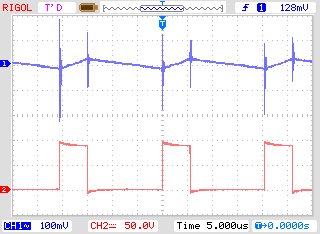
    Now I would like to try the two operating modes (Synchronous and Discontinuous Operation) using Jump1 but strangely there seems to be no difference of Vsw with and without a jumper.
    To better understand I am attaching a screenshot.

    CH1 - Vout(ac) 100mV/div
    CH2 - Vsw(dc) 50V/div

    I think that currently the system operates at about 93% efficiency.
    In fact, with 90V input, the absorption is 570mA with a 2A resistive load at the output.
    Quite in line with the provisions of the charts on page 1 of the AN-1713.

    As soon as I let I know more information.
    I hope you manage to reproduce my working conditions.
    As soon as possible I should produce 30 PCB of a product in which the converter is used.
    I would be grateful if you could confirm the success of the project.
    Thank you.

    Stefano

  • Hi Stefano,

    It's nice to hear that you got the board working.
    Yes, I will confirm the WEBENCH design ASAP.
  • Hi Stefano,

    Sorry for the delay.

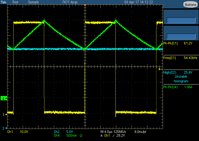
    I have reproduced the WEBENCH design and it's confirmed to be good.  Please see attached.

    BTW, the working scope bench only has a max 60V supply and I did ran the board on at 80V bench setup without any issue.

    Test condition:  Vin=60V, Vout =~24V, Iout =2A, Freq.= 50KHz.

    Ch1= SW node

    Ch2= Vout

    Ch4= Inductor current

    Below is a picture of the modified 12V EVM to 24V.