My customer has some serious problems with the LM5175 which thy need to clarify before production. Instability in the Evaluation Boards and excessive Standby Current. They have oscilloscope plots which will clarify the problems.
]Customer already laid out a PCB in anticipation of using the LM5175 in quantity and purchased a couple of evaluation boards (TPS25740BEVM-741 and TPS25740EVM-741) to give them a run beforehand. Problems with both evaluation boards became apparent when testing for STANDBY Current Drain. Three Oscilloscope Plots are attached and I will explain each. Basically both boards were operated with no load and default to 5Volts out. The input voltage was not below 12Volts so the boards were in Buck Mode for this test.
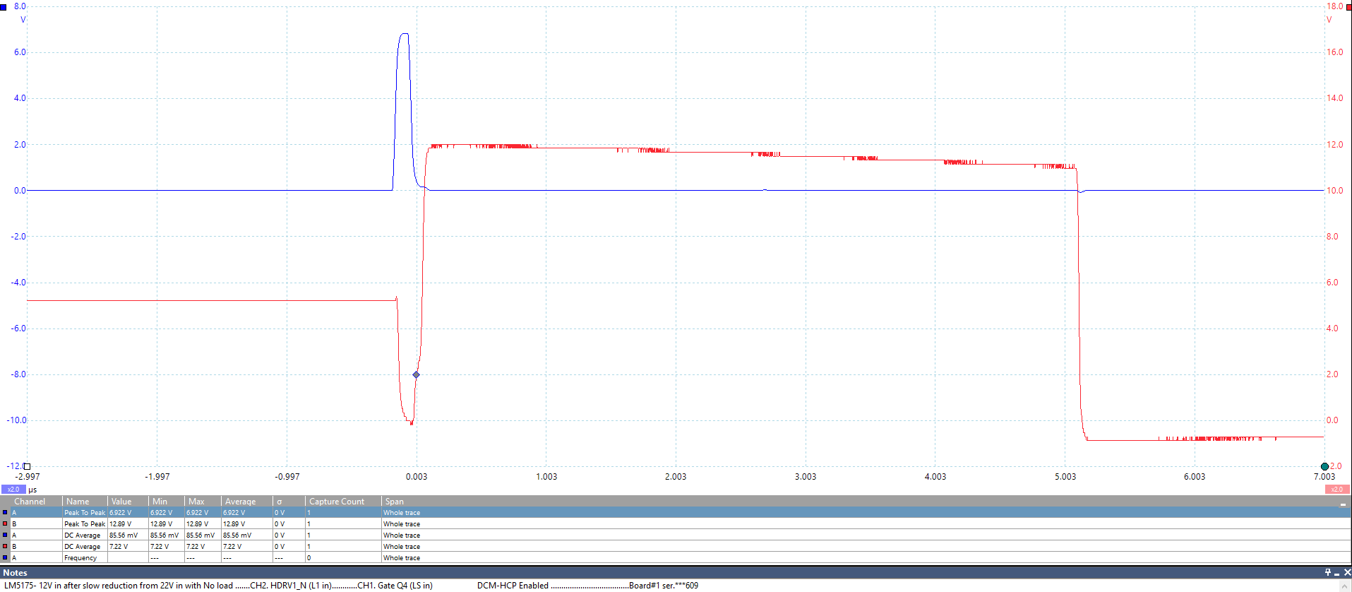
The oscilloscope points are the Gate Drives for incoming Hi and Lo FETs. From the evaluation schematic these are designated HDRV1_P and LDRV1.
Plot#1 has 22Volts input and is drawing 2.0mA. The input voltage can be slowly reduced to 12Volts and the board still draws about 2.0mA and appears stable - with some ringing.
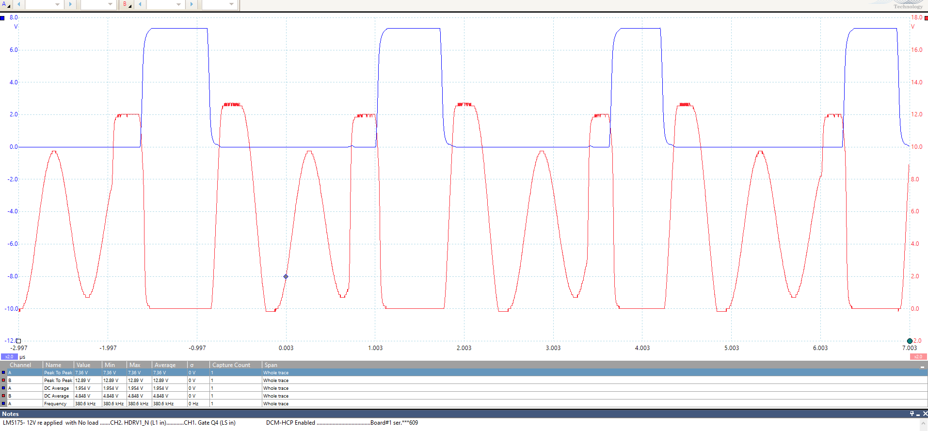
However on Plot#2, on the same board, the input voltage was briefly removed and reinstated. The board immediately became unstable and would not recover stability until the input voltage was increased to 20.88Volts. In this state, at 12Volts the current drain was around 18 to 20mA on several tests. As the input
voltage was increased, the current drain reduced slightly but suddenly dropped at 20.88Volts on all tests.
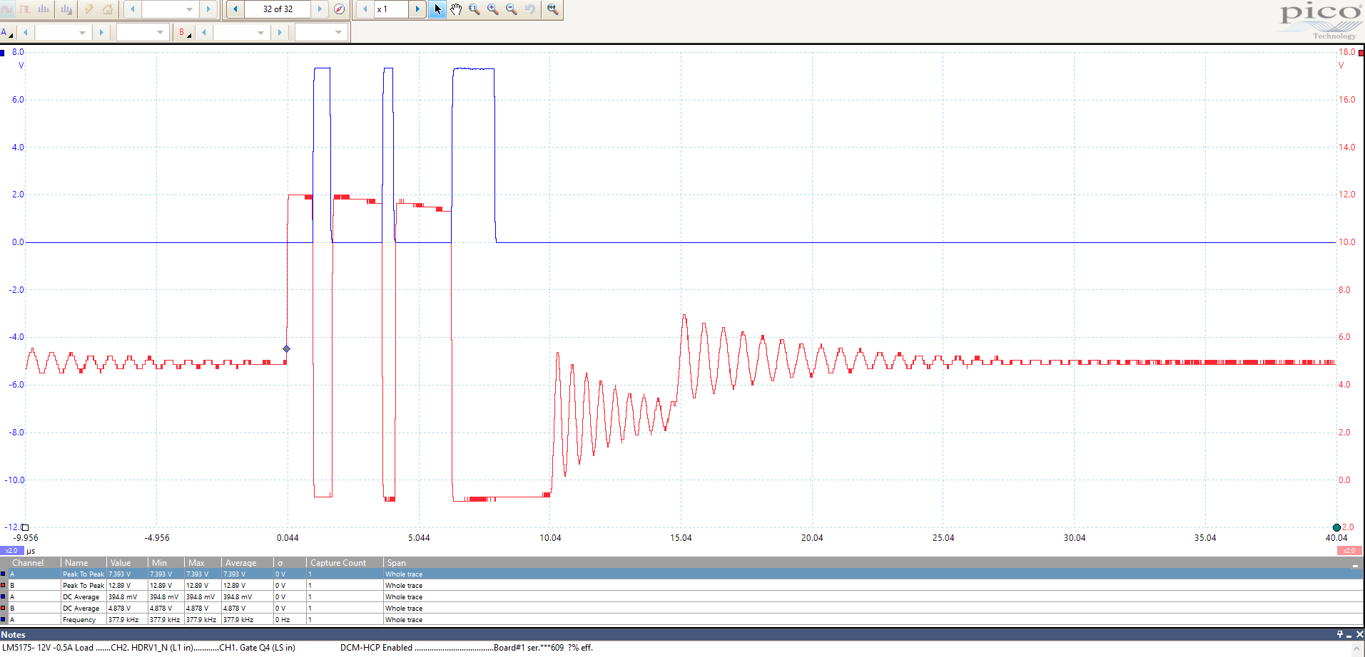
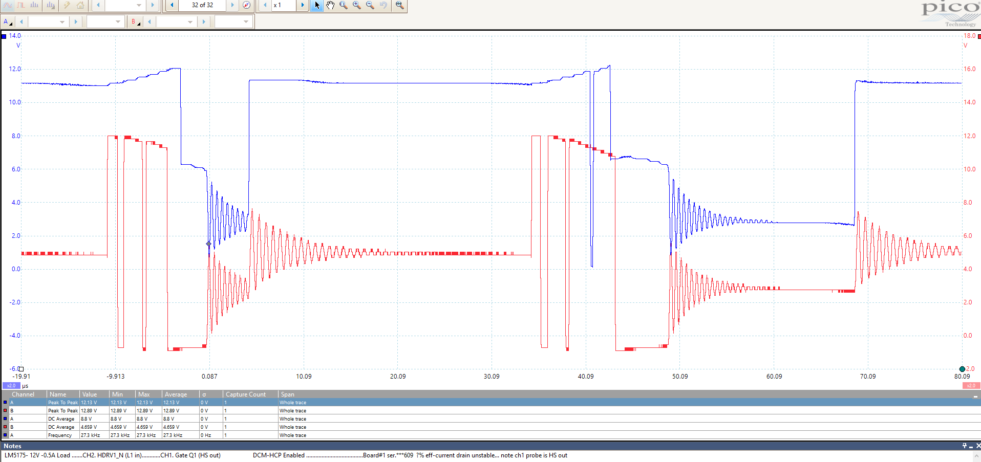
Plot#3 is the second Evaluation Board with 12Volts input and no load but it draws 30mA. This is constant and indicates a fault. In an effort to isolate the fault condition, I removed Q6 and R33 but the current drain remains at 30mA and the waveform is constant i.e. no idle periods for a no load condition.
Can you advise as to what no load current drain we should expect?
The files are attached as pdfs and Picoscope data files
I will send those 6 files attachments in separate message.
Best Regards,