This thread has been locked.

If you have a related question, please click the "Ask a related question" button in the top right corner. The newly created question will be automatically linked to this question.

TPS65400 ev-kit: discrepancy SW to HW

Other Parts Discussed in Thread: USB2ANY, TPS65400EVM-678, TPS65400

Dear,

I received the TPS65400EVM-678 together with USB2ANY and installed PI-Commander Version 0.8.5.

Connection to device works OK, ev-kit starts. I found following issues:

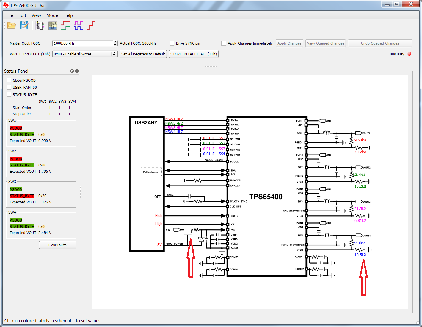
  • SW is asking if it should enable powering the EV-KIT (dialog window when program started + it shows the power switch on the "Home" screen, but ev-kit doesn't have connection from J13 to VDDD). Is the SW expecting more then what is real or schematic is outdated?
  • Resistive dividers on the PCB doesn't fit with SW expectations -> values on the screen doesn't fit to voltages measured. As well, there is discrepancy in values shown on "Home" screen and in ev-kit schematic
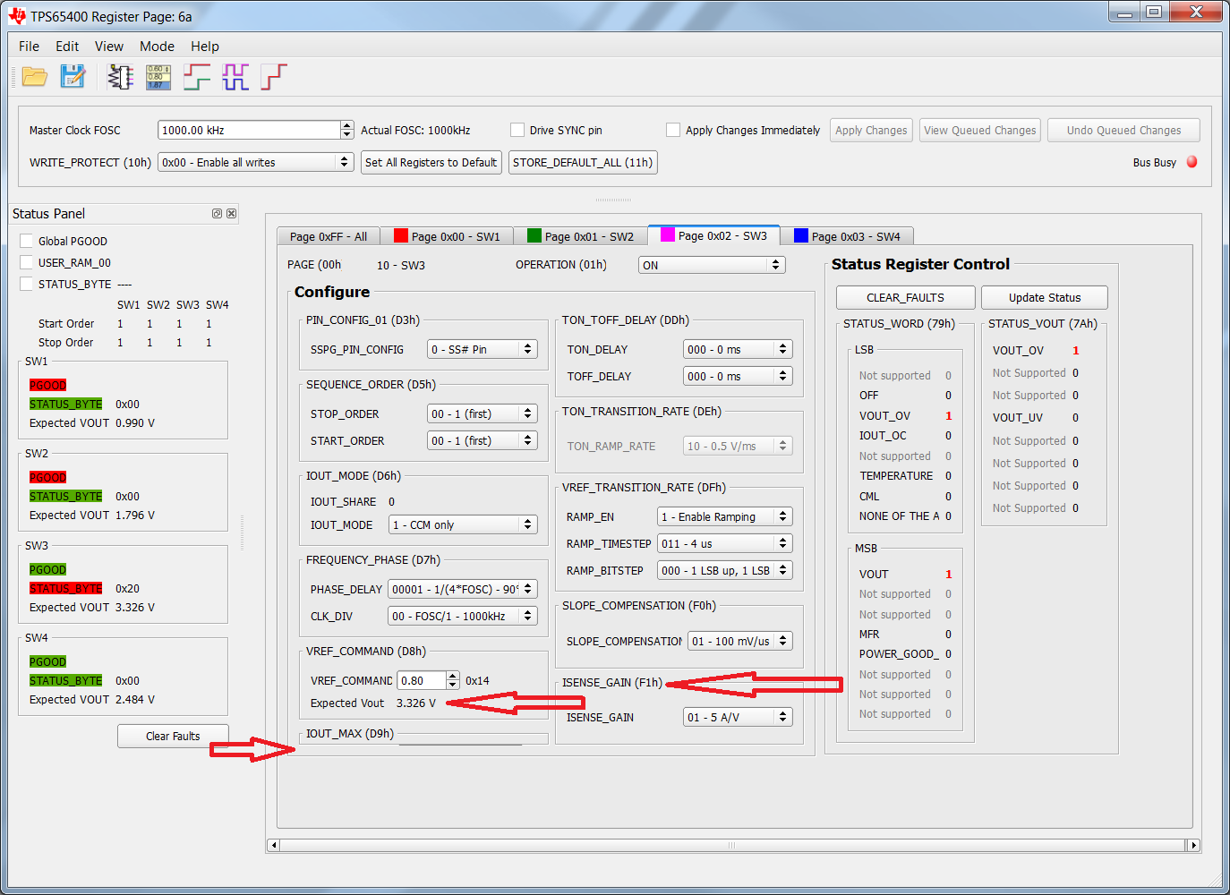
  • On the "Registers" screen there are several bugs:
    • IOUT_MAX item is displayed just partially and can't be altered
    • VREF_COMMAND show wrong voltage
    • Item ISENSE_GAIN (F1h) is may be redundant - datasheet of TPS65400 doesn't show such feature to be implemented
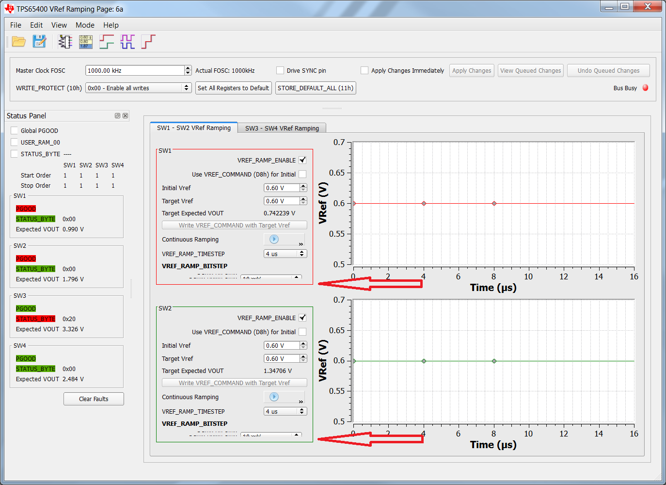
  • On the "Ramping" screen, below VREF_RAMP_BITSTEP there is some item partially hidden - can't be altered

Note that I'm running Win7 - so it should be not  a compatibily issue.

I would also appreciate answer to my older post: e2e.ti.com/.../515217

Thanks in advance for your feedback!

Jiri

  • Dear team,

    I am supporting this customer with this problem with the TPS65400.

    I received this other information:

    These are snapshots with highlighted issues in GUI:

    Could you please advice?

    Thank you very much for your help.

    Best regards,


    Massimiliano De Cristofaro

    Application Support Engineer - Power Management

    ASKTEXAS DiamondLane – EMEA Distribution Support

    Texas Instruments Deutschland

  • Dear Team,

    I received another question from the customer.

    in the datasheet section 8.3.14 it is written that "programming header needs to connect to the SCL, SDA, CE, VDDD, and DGND lines " and so there is no mention about Vin.

    The customer tried to supply VDDD (propagating +3V3_EXT through schottky diode to VDDD, please refer to the ftp.ti.com/.../TSC3060EVM_SBAU199.pdf) but without success.


    Could you please said if Vin is needed or not? In case no, could you please suggest a proposal of how to do this procedure with the EVM?

    Thanks a lot for your support.


    Best regards,

    Massimiliano De Cristofaro

    Application Support Engineer - Power Management

    ASKTEXAS DiamondLane – EMEA Distribution Support

    Texas Instruments Deutschland
  • Hi Massimiliano / Jiri,

    I've moved the post to the isolated DC/DC as this PMIC is supported by the isolated DC/DC team.
  • Need to apply VIN voltage in the test, it's power supply for the EVM. After we have VIN voltage, we need to connect USBTO ANY with our EVM and then open the software for the conenction.
    thanks!
  • Hi Eric,
    I know that VIN is the supply for EVM. But paragraph 8.3.14 of datasheet suggest to first write right configuration data to memory (connecting only SCL, SDA, CE, VDDD, GND) without input power rails connected to prevent unwanted start with wrong setup.
    In case you are TI employee, could you give me a direct call?
  • Yes, you are right, J13 doesn't connect to VDDD, will not power up USBTO ANY.

    Some errors of SW which you point out is right, i need to connect with SW team for the change.

    thanks a lot for your feedback.

    Item ISENSE_GAIN (F1h) function is at DS's page 54, you can check the detail description.

    thanks!

  • Eric Guo1 said:

    Yes, you are right, J13 doesn't connect to VDDD, will not power up USBTO ANY.

    Some errors of SW which you point out is right, i need to connect with SW team for the change.

    thanks a lot for your feedback.

    Item ISENSE_GAIN (F1h) function is at DS's page 54, you can check the detail description.

    thanks!

    Hello TI team,

    any update since 2016-06-03 (2 wks)?

    Thanks in advance for answer, Jiri

  • Hi Jiri,

    I am still working on that, this is RTM part, i need more time for the change.
    do you have any other question in your design?
    thanks!
  • Hello Eric,

    since it is already over 1 month - is there a chance to get fixed software tool for TPS65400? Our board where your chip is used is going to come next week. I wanted to use it to setup the chip to the right sequence, but it seems that I will be forced to use general purpose i2c tools instead (and assembly the frames manually, which is painful).

    Thanks for any update,

    Jiri 

  • Hi Eric Guo,

    You answered only half of my questions. Please reply as well to the rest:
    On the "Registers" screen there are several bugs:
    *IOUT_MAX item is displayed just partially and can't be altered
    *VREF_COMMAND show wrong voltage
    * On the "Ramping" screen, below VREF_RAMP_BITSTEP there is some item partially hidden - can't be altered
    Now I have my own board on the bench and I can't set all registers so setup script is incomplete.

    Thank you in advance,
    Jiri
  • Hi Jiri,

    how you set the resigsters? do you use I2C or PMbus? will you wirte the progrom for the setting?
    our software may not suitable for your boards, in my opinion, you will use your MCU to configure TPS65400, am i right? if you not use I2C or PMbus in our system board, you need to connect with disty to see whether they can help you configure TPS65400 with test board. TI could not configure the IC to every customer. do you have any local FAE? could you connect with them?
    thanks!

    Eric