This thread has been locked.

If you have a related question, please click the "Ask a related question" button in the top right corner. The newly created question will be automatically linked to this question.

PSE and PD in One device

Other Parts Discussed in Thread: TPS23861

Hi,

I am just wondering any one did this before. I have a requirement to make a POE device which will act as PSE and PD as well.

This Device has 2 Ethernet port. First port will get the power from a external PSE and the second port will source the power to the External PD.

My requirement is to charge a 24 V or 48 V Battery as well and in the absence of external PSE, the battery has to feed the Power for the External PD.

Any one did this kind  before or Any special guidelines for such design ?

With Regards,

VA


  • Hi VA,

    We do not have an integrated PSE/PD IC. Do you have a block diagram of what exactly you want to do in your applicaiton?

  • Hi Darwin,

    Our requirement is to take the power from a existing Standard PSE and PD link, Charge the battery and incase of absence of power from the External PSE, then the External PD would be powered by Battery backup.  Even in case of  weak or faulty battery, the External PD should not get disturbed with the original External  PSE power.  We have done few options and I would like to take your feedback on the same which is feasible.  Please note the External PD what are going to connect is going to take a maximum 4 W Power (it may be in sleep mode often)  and the MCU in our custom design may take 3W and the remaining power we would like to charge in a battery. 

    Option 1:


    Option 2 

    Option 3:

    Thank you once again for your time. 


    With Regards,

    VA

  • HI VA,

    For option 1. There is no communication between the PSE and the 'IEEE802.3af' RJ45 PD. There needs to be a PSE (that is the load of the 'TPS PD') to detect and classify that PD. Otherwise, you will be hot plugging in the PD (which defeats the purposes of PoE).

    PMP5177 is a good design to start off your efforts.

    For ORing the 24V adapter at the output, I recommend looking into our ORing controller in the below link.

    http://www.ti.com/lsds/ti/power-management/oring-controller-products.page?paramCriteria=no


    For option 2. In order to be IEEE compliant, you must power the PD through 2 of the 4 pairs. It looks like from the block diagram that one RJ45 ethernet port will power the 'TPS PD' and 'IEEE802.3af' RJ45. If you want to implement something like this (two ports of the PSE through 4 pairs), it will not be IEEE compliant.

    Also, for the 48V battery block, it has to tap from the 48V of the output of the 'TPS PD' similar to option 1. The 48V battery block will load the PSE during detection and classification and the PSE won't start up. The same goes for the 'IEEE802.3af' RJ45 PD load. This needs to placed after the PD with another PSE in order to be IEEE compliant.

    For the 48V adapter ORing, you can look at the different available configurations of adapter ORing in SLVA306A appication note.

    Option 3 has the same issues as option 1 and 2.


  • Hi Darwin,

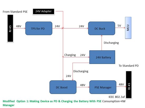
    Thank you for the suggestion. Our Intention is to make a Custom PSE inside the device. When I fed 48 V to the Standard PD via our custom PSE, Will the Standard PD will get ON?  I have modified the Option 1 block Diagram with PSE manager which would be custom with over current protection. Please share your thoughts. 

    Thanks & Regards,

    VA.

  • Hi VA,

    This looks good to me. Yes, as long as the PSE has power from the PSE, adapter, (or battery?), the standard PD should turn on after the PSE detects and classifies it.

    What PSE are you using?

    I recommend you look into our newest PSE just released the TPS23861. It has an EVM you can order if you'd like to evaluate it or use it as a reference circuit.

    http://www.ti.com/tool/TPS23861EVM-612?keyMatch=tps23861&tisearch=Search-EN