This thread has been locked.

If you have a related question, please click the "Ask a related question" button in the top right corner. The newly created question will be automatically linked to this question.

TPS23754: thermal issue for non-isolation design

Part Number: TPS23754

Hello Sir,

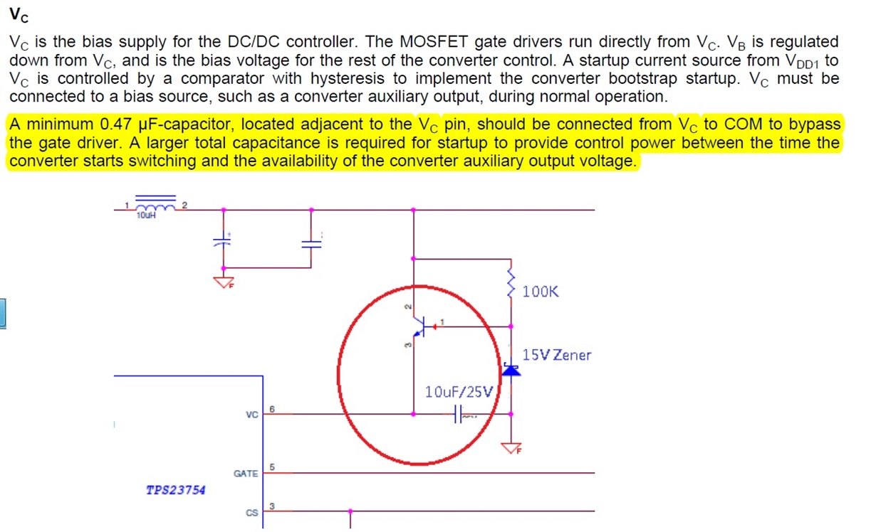
We have implemented a non-isolation POE design by using TPS23754. To generate a bias voltage for Vc (pin 6),

 we used a "transistor series voltage regulator" (please see the following diagram) to generate 14.3V source voltage.

Since there is a requirement to add a minimum 0.47uF capacitor to Vc pin, we set this capacitor to 10uF. It end up a high 

temperature on the transistor of series regulator. We try to reduce the capacitor value to 1uF and then we got 9-deg C down.

My questions are :

1. how to decide the value of capacitor add to Vc pin? (data sheet mention that minimum 0.47uF between Vc and ARTN and 

a larger capacitor to power start up)

2. " a larger capacitor to power startup" How large should it be enough? Is there any formula to calculate it?

3. Can it work If I select a 1uF capacitor for the Vc pin ? Any side effect occur when the capacitor is changed from 10uF to 1uF?

Thanks~

  • Hello Ben,

    Our PD expert has been notified and will reply to you shortly.

    Thanks,
    Thomas A.
  • Thanks a lot! It is important for us since this issue causes reliability problem.
  • Hi Ben,

    1. It depends in how close the cap is to the IC. Typically in an isolated design, the cap will be close to the power transformer so there is a long trace from bias winding to VC of the IC. This is why a 0.47uF cap is required directly at the VC and ARTN pin of the IC and the larger cap will be at the bias winding.

    2. A larger cap is required to provide the gate charge of the switching FET at initial startup without drooping the voltage to UVLO for VC. Typically 22uF is used; however, I have seen 10uF used for similar VC driver. However, looking at the schematic, we used a 9.1V zener and not 15V. Can you try with lower voltage zener?

    3. As described on #2, the cap must not droop when the FET initially starts switching. I recommended keeping with 10uF.

  • Hi Darwin,

    Thanks for your reply. 

    1. For my design, If there is no problem to start up the non isolated PD with full load, is there any other issue should

       be taken into account when  the capacitor of Vc pin is reduced?

    2. When I use lower voltage zener-diode, the temperature of the series regulator (transistor) will be rising up

       due to higher voltage drop between drain and source. 

    3. Besides the thermal issue of series regulator mentioned in # 2, if I decrease Vc, the voltage of MOSFET's gate drive

       will also be decreased. It may increase Rds (ON) of the switching MOSFET since the Vgs of MOSFET fall off.

       Consequently, the MOSFET may consume more power.

    Best Regards,

    Ben

  • Hi Ben,

    What BJT part number are you using; we have tested on the MMBTA06LT1 for a similar VC circuit.
  • Hi Darwin,

    We used NXP BCX56.