A related question is a question created from another question. When the related question is created, it will be automatically linked to the original question.
If you have a related question, please click the "Ask a related question" button in the top right corner. The newly created question will be automatically linked to this question.
The output voltage range0.6-6V.Now my output voltage is 8V.there is no problem.Also, The input voltage range is 6-36V,why the output voltage is so low.
I would like to know the risk when I output voltage is 8v.
LMZ23610 has been designed for an output voltage between 0.8V and 6V.
When the part is overstressed beyond this borders, the proper functionality is not given.
The device could be damaged irreversible. Several other failures can occur before, for example instability of the regulation loop.
For your application I would recommend the LMZ14203H which is a part that was designed for higher output voltages up to 24Vout.
If you have more questions please don't hesitate to ask!
I want to know that Whether the internal circuit is limited or dissipated power problems, such as internal inductance saturation factors, etc. At present my application is 8V8A, I would like to understand the true and the internal principle of not reaching 8v or higher
Yes sorry, my fault. Forgot that your application needs up to 10A? Is that right?
As you mention, probably the inductor and the IC are not rated for such high voltages or output powers.
It might be the case that your application works right now, but stressing the device beyond its limits may cause permanent damage to it. The functional operation of the device can not be guaranteed under these stress conditions.
Image you drive a hand shifted car and the motor rotation speed is always in the red area. The car will drive, but how long? The engine suffers from this operation mode and the probability that the engine will be destroyed within a short time is quite high.
I did a quick research and unfortunately found no module that fits with your requirements.
Utilize Webench and have a look at the suggested options.
I talked to some engineers and there are some additional points I can give you.
The device might be able to operate with your requirements, nevertheless functionality is not guaranteed.
1. Thermal limits
Be sure that thermal limit is not exceeded. The maximum junction temperature is 150C. The device will go into thermal shutdown at 165C and will turn on again with a hysteresis of 15C (see datasheet point 6.5.). So you have to make sure that your application provides enough cooling capacity.
2. Current limits
The current limit section in the datasheet (refer to section 7.3.4.) says that current is sensed through the low side FET and the high side FET.
The overcurrent shut off for the low side is 13A and for the high side is 16A as typical values.
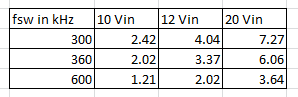
Depending on your input voltage and switching frequency you have different ripple currents. I calculated some for you.
These are peak to peak values in ampere. So depending on your conditions you might reach current limit and the device turns off.
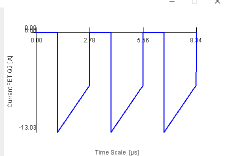
The following picture shows you as an example the current through the low side FET with 20V input, 8V output @ 360kHz switching frequency.
With this conditions or some other conditions, the current limit might be triggered (13A is a typical value, it can be slightly below).
You can use the Power stage designer tool to calculate these values and it also gives you some graphs. Perhaps this can help you.
Thanks for your answer.Now I have another problem, that is, when I put the output voltage of 5V, the outut short circuit and then open and found that there will be 100us output of more than 10V.