This thread has been locked.

If you have a related question, please click the "Ask a related question" button in the top right corner. The newly created question will be automatically linked to this question.

LM22676 instead of a TPS5430

Other Parts Discussed in Thread: TPS5430, LM22676, TPS54360, LM5576

Hi there,

Previously I was using a TPS5430 to turn a 24V into a -24V. It was working rather nicely.

Unfortunately, I have found that the input power can be as high as 30V now ... thats +6V on the input. When this happens, the TPS5430 sparks and lets its smoke out.

I am thinking of trying the LM22676 instead of the TPS5430 because it can handle 6V more on the input. It also has the same footprint and circuit. I have a new design which simply requires replacing the bias resistor divider with ones which suit the LM22676.

Does anyone see any problems with this approach ?

thanks

Matt

  • Hi Matt,

    Are you using the IC in the inverting buck boost condition? Your idea of using LM22676 which has 6V more than TPS5430 seems logical. Although i am quite concerned that you might violate the input VIN abs max value if you use the IC in the inverting buck boost configuration.

    The reason is because the effective VIN is now equal to VIN - (-VOUT) which is now based on your design is 54V. The other pin that quite a concern is the BOOT pin, please make sure that the pin did not exceed it's rating.

    Do you have a schematic that you can share with us? So that we can review the design and double check if anything will violate the pin recommended operating conditions. 

    Thanks

    -Arief 

  • Hi Arief,

    Thanks for your reply it is nice to have the support.

    My schematic is the same as the reference schematic for the LM22676 (which is the same for the TPS5430). The Vin potential is 48V or a little more and the Vo potential is 24V.

    If this input voltage is too large, then is there a good replacement I can use ?

    I would prefer the replacement to be as simple as these circuits.

    thanks

    Matt

  • Hi Matt,

    I assume that your 48V Vin is referenced to Vout. Therefore you need a 60V input rated part.
    I think you might be able to use this following part: TPS54360
    http://www.ti.com/lit/ds/symlink/tps54360.pdf

    There is also a detailed design procedure available for the family of this part
    http://www.ti.com/lit/an/slva317b/slva317b.pdf

    Let me know if this would work for you. 

    Thanks

    -Arief

  • Matt,

    What is your required load current? I see that LM5576 which is also a SIMPLE SWITCHER device might work. Its max input voltage is 75V.

    Regards,
    Akshay

  • Hi,

    Thanks for the heads up ... I will look into this part ... it appears that it has a different footprint/circuit, but it may be worth a shot.

    thanks

    Matt

  • Hi,

    This looks like a good option. The circuit is slightly different, however not too far off what I already have on the PCB. I think this may work for me.

    thanks

    Matt

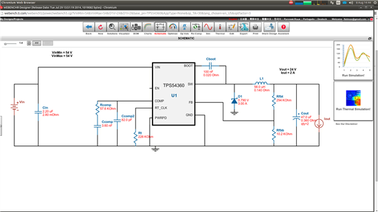
  • OK - I am now trying to use the TPS54360 in TINA.

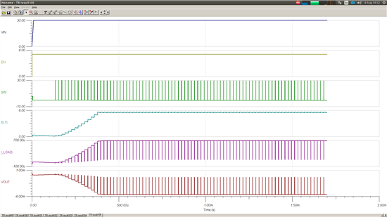
    I am actually trying to get -24V from the output. So I have switched gnd and vout ... I have attached the reference schematic and resulting output ... the output doesn't make it to -24V ... not sure why ... also Any idea how to stop these awful pulses which occur each time the switch activates ?

  • Hi Matt,

    Are you able to get things working if the VOUT and GND is in the normal buck position (No reverse)?
    It looks like that you might be hitting a current limit or some sort since your current is quite high on IL1 (6A). How much current do you put on the load? 

    Do you have a capture of schematic for the TINA spice after you reverse the GND and VOUT? I believe if you have the negative buck configuration, everything has to be referenced to -VOUT instead of GND. 

    Another thought is that the compensation component for the negative buck configuration is also different since there is an extra zero and poles, so you might have to change the compensation components if you configure this as a negative buck configuration.  

    Thanks

    -Arief