This thread has been locked.

If you have a related question, please click the "Ask a related question" button in the top right corner. The newly created question will be automatically linked to this question.

UCD9090: Stuck at other comms fault in STATUS_CML register

Part Number: UCD9090

Hi:

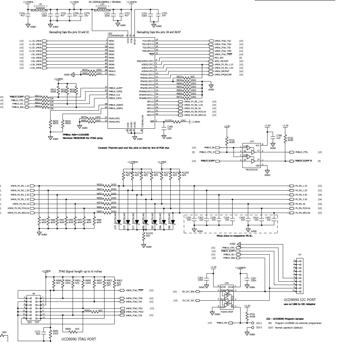
We used UCD9090 for different voltage rails monitoring  showed as below pictures:

Recently we tried to write MFR ID and Revision register through our own PMBUS host, MCU is TI Hercules RM57,  the writing procedure is block write, read and save. Sometime it worked, but sometime not worked, it looks not consistently, is this correct writing procedure? 

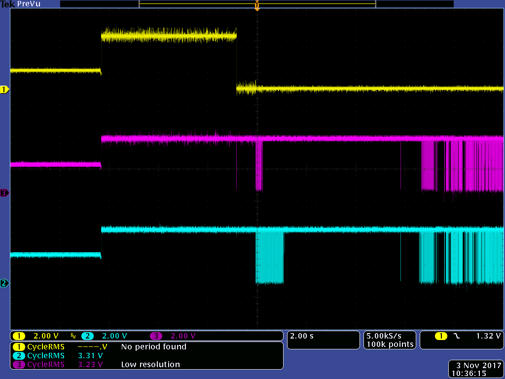
We used TI emulator through Fusion GUI for UCD9090 configuration, it looks no any problem, but after we used our own firmware to write MFR register, UCD9090 keeps reporting Other Comms Fault showed as below:

This fault will assert alert pin and switch off all the rails, so our MCU can't start until we connect TI emulator and run Fusion GUI to switch on rails.

Could you help to let us why this fault is reported as no any communication after power reset? And how can we remove this fault? Does UCD9090 have any command to reset to factory default?

Thanks very much!

Jack

  • Could you please share what your FW did? Did it follow pmbus protocol?

    Did you connect the alert pin to reset or power control pin? I need more information to understand how the alert will power off the power.

    Thanks

    Yihe

  • Hi,

    Please find attached C code and Schematic, if you need more info, please let me know, I think we are following PMBUS protocol as no any issue for reading, only after writing keeps triggering Other comms fault after power reset.

    psdrv.c
    /*
    
    FILE NAME:  PSDRV.c
    
    PURPOSE:
        Provide functions to access the TI UCD device UCD9090 over I2C bus.
    
    
    FUNCTION(S):
    
    
    NOTES:
    
    CHANGE HISTORY:
    $Log: PSDRV.c $
    
    ==============================================================================*/
    
    
    /*==============================================================================
                                  Includes
    ==============================================================================*/
    #include <stdio.h>
    #include <string.h>
    #include <stdlib.h>        // for atoi
    #include "psdrv.h"
    #include "i2c.h"
    #include "diodrv.h"
    #include "strtoupper.h"
    /*==============================================================================
                                  Defines
    
    ==============================================================================*/
    
    /*==============================================================================
                                Type Definitions
    ==============================================================================*/
    #define PSDRV_DBG_LEVEL                                    ( DBG_INFO + 1 )
    
    #define PSDRV_MAX_VOUT                                     ( 9 )
    // Package Error Checking is implemented on the power sequencer & monitor chip
    // PEC may be calculated in any way that conforms to a CRC-8 represented by teh polynominal
    // C(x) = X^8+X^2+X^1+X^0
    #define CRC8_POLYNOMIAL                                    ( 0x107 )
    #define CRC8_START                                         ( 0x00 )
    
    #define PMBUS_READ                                         ( 0x01 )
    #define PMBUS_WRITE                                        ( 0x00 )
    
    #define PSDRV_I2C_REG                                      ( i2cREG1 )
     
    #define NUMBER_OF_MFR_CMD                                  (((PSDRV_CMD_MRF_SERIAL - PSDRV_CMD_MRF_ID) + 1))
    #define MFR_CMD_OFFSET                                     ( PSDRV_CMD_MRF_ID )
    
    #define PSDRV_BUF_LEN_MAX                                  ( 50u )
    
    #define EXT_WD_CONFIG_WDI_ENABLE                           ( 0x79 )
    #define EXT_WD_CONFIG_WDI_DISABLE                          ( 0x00 )
    
    #define PS_COMM_LOST_TIMER_CNT_INTERVAL                    (500u/10u) //500ms
    #define PS_COMM_LOST_CNT_MAX                               ( 3u )
    
    /*==============================================================================
                                    Enums
    ==============================================================================*/
    typedef enum eEXT_WD_CONFIG_REG
    {
        EXT_WD_CONFIG_REG_CONTRL = 0,
        EXT_WD_CONFIG_REG_WDI,
        EXT_WD_CONFIG_REG_RESET_PERIOD,
        EXT_WD_CONFIG_REG_RESET_WDO
    }teEXT_WD_CONFIG_REG;
    
    /*=============================================================================
                                  Structures
    ==============================================================================*/
    
    
    /*==============================================================================
                               Local/Private Constants
    ==============================================================================*/
    
    
    /*==============================================================================
                               Local/Private Variables
    ==============================================================================*/
    static uint8 ucPsAddr;    // this address should match the device address set by PMBUS_ADDR0 and PMBUS_ADDR1 pins
    static uint8 ucBlockBuf[ PSDRV_LEN_MAX ];
    static uint32 ulVoutMode[ PSDRV_MAX_VOUT ];
    static uint8 ucMRFIDActualLen = PSDRV_LEN_MRF_ID;
    /*==============================================================================
                            Local/Private Function Protoypes
    ==============================================================================*/
    
    
    /*==============================================================================
                               Function Definitions
    ==============================================================================*/
    static uint8 psdrv_fnGetReadCmdPEC( uint8 ucCmd );
    static uint8 psdrv_fnGetWriteCmdPEC( uint8 ucCmd );
    static uint8 psdrv_fnCalculatePEC(uint8 ucStartCrc, uint8 *ucData, uint8 ucDataLen);
    static void psdrv_fnDisplayError( FILE *fp, PSDRV_teERRNO teCode );
    static PSDRV_teERRNO psdrv_fnWritePageCmd( uint8 ucPage );
    static PSDRV_teERRNO psdrv_fnWriteCmd( uint8 ucCmd );
    static PSDRV_teERRNO psdrv_fnWriteCmdWithPEC( uint8 ucCmd );
    static PSDRV_teERRNO psdrv_fnGetWatchdogConfig( uint8 *pucData);
    static tucBOOL psdrv_fnCliRead( FILE *fp, uint16 argC, char *argV[], CLI_tzSTATE * pCLIInstance );
    
    /*******************************************************************************
    
    FUNCTION NAME:
        PSDRV_fnCtor
    
    PURPOSE:
        init i2c interface that can be used to write to and read from the UCD9090
    
    INPUTS:
        none
    
    OUTPUTS:
        Always eSTATUS_OK
    
    NOTES:
        i2c interface shall be initialized in SEEP module prior this function is called.
    
    VERSION HISTORY:
    
    *******************************************************************************/
    tuiSTATUS PSDRV_fnCtor( void )
    {
        uchar8 i;
    
        DIODRV_fnSetPmBusCtrl( TRUE );
    
        ucPsAddr = PSDRV_ADDRESS;
    
        //Make sure  i2cInit( i2cREG1 ) had been initialized before this
        psdrv_fnWriteCmd( PSDRV_CMD_CLR_FLT );
    
        //Reset external watchdog during startup to solve WD kick pin stuck issue
        psdrv_fnWriteCmd( PSDRV_CMD_WATCHDOG_RESET);
    
        for( i=0; i< PSDRV_MAX_VOUT; i++)
        {
            ulVoutMode[i] = 0L;
        }
    
        return eSTATUS_OK;
    }
    
    
    /*******************************************************************************
    
    FUNCTION NAME:
        PSDRV_fnRead
    
    PURPOSE:
        read specified length of data using specific command
    
    INPUTS:
        cmd     - PMBUS command byte
        *data   - memory location to hold the received data
        len       - number of bytes to receive, not incluing the PEC byte
    OUTPUTS:
        PSDRV_teERRNO
    
    NOTES:
        Field uiLen doesn't include the PEC byte, but include the block count byte,
        if it's for the block read.
    
    VERSION HISTORY:
    
    *******************************************************************************/
    PSDRV_teERRNO PSDRV_fnRead( uint8 ucCmd,  uint8 *pData, uint16 uiLen)
    {
        PSDRV_teERRNO rtn = PSDRV_eERR_NONE;
    
        // check for invalid inputs
        if( pData == NULL || uiLen == 0 )
        {
            return PSDRV_eERR_INVALID_LEN;
        }
    
        I2C_fnLock(PSDRV_I2C_REG);
    
        // make sure the bus is ready
        i2cReset( PSDRV_I2C_REG );
    
        // Disable I2C during configuration
        i2cSetMode( PSDRV_I2C_REG,  0u);
        // send 1 byte for command
        i2cSetCount(PSDRV_I2C_REG, 1);
        i2cSetSlaveAdd( PSDRV_I2C_REG,ucPsAddr );
    
        // Configure the I2C controller as master transmitter
        i2cSetMode( PSDRV_I2C_REG,I2C_RESET_OUT | I2C_START_COND | I2C_TRANSMITTER | I2C_MASTER );
        if( i2cSend(PSDRV_I2C_REG,1, &ucCmd) != eSTATUS_OK )
        {
            //i2cReset( PSDRV_I2C_REG );
            I2C_fnUnlock(PSDRV_I2C_REG);
            return PSDRV_eERR_TX_TIMEOUT;
        }
    
        OSTimeDly(2);
    
        // now receive from power sequencer chip, add one byte for PEC, end with STOP
        i2cReset( PSDRV_I2C_REG );
    
        i2cSetMode( PSDRV_I2C_REG,  0u);
        i2cSetCount(PSDRV_I2C_REG,  uiLen + 1);
    
        i2cSetSlaveAdd( PSDRV_I2C_REG,ucPsAddr );
    
        i2cSetMode( PSDRV_I2C_REG,I2C_RESET_OUT | I2C_START_COND | I2C_STOP_COND | I2C_MASTER );
    
        if( i2cReceive(PSDRV_I2C_REG, uiLen+1, pData ) != eSTATUS_OK )
        {
            i2cReset( PSDRV_I2C_REG );
            I2C_fnUnlock(PSDRV_I2C_REG);
            return PSDRV_eERR_RX_TIMEOUT;
        }
        I2C_fnUnlock(PSDRV_I2C_REG);
    
    
        return rtn;
    
    }
    
    /*******************************************************************************
    
    FUNCTION NAME:
        PSDRV_fnWriteBlockWithPEC
    
    PURPOSE:
        write specified length of data using specific command
    
    INPUTS:
        cmd     - PMBUS command byte
        *data   - memory location to hold the sending data
        len       - number of bytes to send, not incluing the PEC byte
    OUTPUTS:
        PSDRV_teERRNO
    
    NOTES:
        Field uiLen doesn't include the PEC byte, but include the block count byte,
        if it's for the block write.
    
    VERSION HISTORY:
    
    *******************************************************************************/
    PSDRV_teERRNO PSDRV_fnWriteBlockWithPEC( uint8 ucCmd,  uint8 *pData, uint16 uiLen)
    {
        uint8 ucCrc;
        uint8 ucTxLen;
        PSDRV_teERRNO rtn = PSDRV_eERR_NONE;
        uint16 i;
        uint8  ucBuf[ PSDRV_BUF_LEN_MAX ];
    
        // check for invalid inputs
        if( pData == NULL || uiLen == 0 )
        {
            return PSDRV_eERR_INVALID_LEN;
        }
    
        ucBuf[ 0 ] = ucCmd;
        ucBuf[ 1 ] = uiLen;
    
        for(i = 0; i < uiLen; i++)
        {
            ucBuf[i+2] = *(pData + i);
        }
    
        ucCrc = psdrv_fnGetWriteCmdPEC(ucCmd);
        ucCrc = psdrv_fnCalculatePEC( ucCrc, &ucBuf[1], uiLen+1);
    
        ucBuf[uiLen+2] = ucCrc;
    
        ucTxLen = uiLen+3;
    
        I2C_fnLock(PSDRV_I2C_REG);
    
        // make sure the bus is ready
        i2cReset( PSDRV_I2C_REG );
    
        // Disable I2C during configuration
        i2cSetMode( PSDRV_I2C_REG,  0u);
    
        i2cSetCount(PSDRV_I2C_REG, ucTxLen);
    	
        i2cSetSlaveAdd( PSDRV_I2C_REG,ucPsAddr );
    
        // Configure the I2C controller as master transmitter
        i2cSetMode( PSDRV_I2C_REG,I2C_RESET_OUT | I2C_START_COND | I2C_TRANSMITTER | I2C_MASTER );
        if( i2cSend(PSDRV_I2C_REG,ucTxLen, ucBuf) != eSTATUS_OK )
        {
            I2C_fnUnlock(PSDRV_I2C_REG);
            return PSDRV_eERR_TX_TIMEOUT;
        }
    
        OSTimeDly(2);
    
        I2C_fnUnlock(PSDRV_I2C_REG);
    
    
        return rtn;
    
    }
    /*******************************************************************************
    
    FUNCTION NAME:
        PSDRV_fnReadBlockWithPEC
    
    PURPOSE:
        Send PMBus Block Read with PEC message and check the received data with PEC code
    
    INPUTS:
        cmd     - PMBUS command byte
        *data   - the memory location to hold the received data
        len       - number of bytes to read, only include the data bytes
    
    OUTPUTS:
        PSDRV_teERRNO
    
    NOTES:
        The uiLen counter doesn't include the block count byte and PEC byte.
    
        Message format for Block Read with PEC:
        ||S | Address|Wr|| A ||CommandCode|| A
        ||Sr| Address|Rd|| A ||BlockCount      || A ||DataByte1||  A
                                               ||DataByte2|| A|| ...
                                               ||DataByteN|| A ||PECByte|| N| P|
    
    VERSION HISTORY:
    
    *******************************************************************************/
    
    PSDRV_teERRNO PSDRV_fnReadBlockWithPEC( uint8 ucCmd,  uint8 *pData, uint16 uiLen)
    {
        uint8 ucCrc;
        uint8 ucLen;
        PSDRV_teERRNO rtn = PSDRV_eERR_NONE;
    
        if( uiLen > ( PSDRV_LEN_MAX - 2 ) )
        {
            return ( PSDRV_eERR_INVALID_LEN );
        }
    
        // add the length with block count byte
        rtn = PSDRV_fnRead( ucCmd, ucBlockBuf, uiLen+ 1 );
    
        // check the received block count
        ucLen = ucBlockBuf[0];
    
        // if it's greater than the one we expect, we might not provide enough memory to hold the data
        if( ucLen > uiLen )
        {
            *pData = ucLen;
            KDBG( PSDRV_DBG_LEVEL, "PSDRV: try to read %d bytes but received %d bytes \r\n",uiLen, ucLen );
            return ( PSDRV_eERR_INVALID_LEN );
        }
        else if( ucLen < uiLen )
        {
             uiLen = (uint16)ucLen;
        }
    
        // calculate PEC code that we expect
        ucCrc = psdrv_fnGetReadCmdPEC( ucCmd );
        ucCrc = psdrv_fnCalculatePEC( ucCrc, ucBlockBuf, uiLen+1);
    
        // compare with the one that we reveived
        if( ucCrc != ucBlockBuf[ uiLen+1 ] )
        {
             KDBG( PSDRV_DBG_LEVEL, "PSDRV: crc error \r\n" );
             rtn = PSDRV_eERR_CRC;
        }
        else
        {
            ucBlockBuf[ uiLen+1 ] = 0;
            memcpy( pData, &ucBlockBuf[1], (uiLen+1) );
        }
    
       return rtn;
    }
    /*******************************************************************************
    
    FUNCTION NAME:
        PSDRV_fnReadByteWithPEC
    
    PURPOSE:
        Send PMBus Byte Read with PEC message and check the received data with PEC code
    
    INPUTS:
        cmd     - PMBUS command byte
        *data   - the memory location to hold the received data
    
    OUTPUTS:
        PSDRV_teERRNO
    
    NOTES:
    
        Message format for Byte Read with PEC:
        ||S | Address|Wr|| A ||CommandCode|| A
        ||Sr| Address|Rd|| A ||DataByte   || N| P|
    
    VERSION HISTORY:
    
    *******************************************************************************/
    
    PSDRV_teERRNO PSDRV_fnReadByteWithPEC( uint8 ucCmd,  uint8 *pData )
    {
        uint8 ucCrc;
        PSDRV_teERRNO rtn;
    
        rtn = PSDRV_fnRead( ucCmd, pData, PSDRV_LEN_RECV_BYTE );
        KDBG( PSDRV_DBG_LEVEL, "PSDRV RXB: %02X %02X ", pData[0],pData[1] );
    
        if( rtn == PSDRV_eERR_NONE )
        {
            // calculate PEC code that  we expect
            ucCrc = psdrv_fnGetReadCmdPEC( ucCmd );
            ucCrc = psdrv_fnCalculatePEC( ucCrc, pData, PSDRV_LEN_RECV_BYTE );
    
             // compare with the one that we reveived
            if( ucCrc != pData[ PSDRV_LEN_RECV_BYTE ] )
            {
                 KDBG( PSDRV_DBG_LEVEL, "CRC error, expect %02X \r\n", ucCrc);
                 rtn = PSDRV_eERR_CRC;
            }
       }
    
       return( rtn );
    }
    /*******************************************************************************
    
    FUNCTION NAME:
        PSDRV_fnReadWordWithPEC
    
    PURPOSE:
        Send PMBus Read Word with PEC message and check the received data with PEC code
    
    INPUTS:
        cmd     - PMBUS command byte
        *data   - the memory location to hold the received data
    
    OUTPUTS:
        PSDRV_teERRNO
    
    NOTES:
    
        Message format for Byte Read with PEC:
        ||S | Address|Wr|| A ||CommandCode|| A
        ||Sr| Address|Rd|| A ||DataByteLow||A ||DataByteHigh|| N| P|
    
    VERSION HISTORY:
    
    *******************************************************************************/
    
    PSDRV_teERRNO PSDRV_fnReadWordWithPEC( uint8 ucCmd,  uint8 *pData )
    {
        uint8 ucCrc;
        PSDRV_teERRNO rtn;
    
        rtn = PSDRV_fnRead( ucCmd, pData, PSDRV_LEN_RECV_WORD );
    
        KDBG( PSDRV_DBG_LEVEL, "PSDRV RXW: %02X %02X %02X ", pData[0],pData[1],pData[2] );
    
        if( rtn == PSDRV_eERR_NONE )
        {
            // calculate PEC code that  we expect
            ucCrc = psdrv_fnGetReadCmdPEC( ucCmd );
            ucCrc = psdrv_fnCalculatePEC( ucCrc, pData, PSDRV_LEN_RECV_WORD );
    
             // compare with the one that we reveived
            if( ucCrc != pData[ PSDRV_LEN_RECV_WORD ] )
            {
                KDBG( PSDRV_DBG_LEVEL, "CRC error, expect %02X\r\n", ucCrc );
                rtn = PSDRV_eERR_CRC;
            }
       }
    
       return( rtn );
    }
    /*============================================================================*/
    /*!
    
    \brief
        Read all status information
    
    \param[in] pfData pointer to memory location to store the read data
    
    \retval PSDRV_eERR_NONE if the function was successful
    
    */
    /*============================================================================*/
    PSDRV_teERRNO PSDRV_fnGetStatus( uint8 *pucData)
    {
    
        PSDRV_teERRNO teRet;
        uint16 ucData;
        uint8  ucBuf[ PSDRV_BUF_LEN_MAX ];
    
        teRet = PSDRV_fnReadWordWithPEC( PSDRV_CMD_STATUS_WORD, pucData );
        if( teRet != PSDRV_eERR_NONE )
        {
            return( teRet );
        }
        pucData++;
        pucData++;
    
        teRet = PSDRV_fnReadByteWithPEC( PSDRV_CMD_STATUS_CML, (uint8*)&ucData );
        *pucData++ = (uint8)ucData;
    
        teRet = PSDRV_fnReadBlockWithPEC( PSDRV_CMD_MFR_STATUS, ucBuf, PSDRV_LEN_MRF_STATUS );
        if( teRet != PSDRV_eERR_NONE )
        {
           return( teRet );
        }
        *pucData++ = ucBuf[3];
        *pucData++ = ucBuf[2];
        *pucData++ = ucBuf[1];
    	
        return( teRet );
    
    }
    /*============================================================================*/
    /*!
    
    \brief
        Send READ_VOUT command for specific page number
    
    \param[in] ucPage page number, from 0 to 8
    \param[in] pfData pointer to memory location to store the read data
    
    \retval PSDRV_eERR_NONE if the function was successful
    
    */
    /*============================================================================*/
    
    PSDRV_teERRNO PSDRV_fnGetVout( uint8 ucPage, float32 *pfData)
    {
        PSDRV_teERRNO teRet;
        uint32 ulExp;
        uint16 uiValue;
    
        //voltage value is calculated using the equation Voltage = V * 2^x
        // where V is a 16-bit unsigned binary integer mantissa from READ_VOUT
        // X is the signed 5-bit twos-complement binary integer exponent from VOUT_MODE
        //
    
        // set the page
        teRet = psdrv_fnWritePageCmd( ucPage );
    
        if( teRet != PSDRV_eERR_NONE )
        {
             return( teRet );
        }
    
        // read VOUT_MODE for current page
        if( ulVoutMode[ucPage] == 0L )
        {
        teRet = PSDRV_fnReadByteWithPEC( PSDRV_CMD_VOUT_MODE, ucBlockBuf );
    
        if( teRet != PSDRV_eERR_NONE )
        {
             return( teRet );
        }
            ulVoutMode[ucPage] = (uint32) 1 <<((~ucBlockBuf[0] + 1 )&0x1F);
        }
        ulExp = (uint32)ulVoutMode[ucPage];
    
        // read READ_VOUT for current page
        teRet = PSDRV_fnReadWordWithPEC( PSDRV_CMD_READ_VOUT, ucBlockBuf );
        if( teRet != PSDRV_eERR_NONE )
        {
            teRet = PSDRV_fnReadWordWithPEC( PSDRV_CMD_READ_VOUT, ucBlockBuf );
        }
        if( teRet == PSDRV_eERR_NONE )
        {
             uiValue = (uint16)ucBlockBuf[1];
             uiValue = (uiValue << 8) + ucBlockBuf[0];
    
             // Voltage = V * 2^x
             *pfData = (float32)uiValue/(float32)ulExp;
        }
        return( teRet );
    }
    /*============================================================================*/
    /*!
    
    //fn  psdrv_fnCalculatePEC
    
    \brief
        Calculate PEC
    
    \param[in]
        ucData - pointer to data buffer
        ucDataLen - data buffer length
    
    \return
        Calculated CRC value
    
    \details
    
        Package Error Checking is implemented on the power sequencer & monitor chip.
        PEC is calculated in the order of the bits as received, including addresses and read/write
        bits.
    
    \code
    REVISION HISTORY:
    
    Version: 1.00    Date: 28-Jun-2015    By: Holly Zhou
        - Created
    
    \endcode
    
    */
    /*============================================================================*/
    static uint8 psdrv_fnCalculatePEC(uint8 ucStartCrc, uint8 *ucData, uint8 ucDataLen)
    {
        uint8  crc;
        uint16 loop_count;
        uint8  bit_counter;
    
        crc = ucStartCrc;
    
        for(loop_count = 0; loop_count < ucDataLen; ++loop_count)
        {
            crc ^= *(ucData + loop_count);
            for (bit_counter = 8; bit_counter > 0; --bit_counter)
            {
                if(crc & 0x80)
                {
                    crc = (crc << 1) ^ CRC8_POLYNOMIAL;
                }
                else
                {
                    crc = (crc << 1);
                }
            }
    
        }
    
        return crc;
    }
    
    /*******************************************************************************
    
    FUNCTION NAME:
        psdrv_fnGetReadCmdPEC
    
    PURPOSE:
        Calculate the PEC code for read command
    
    INPUTS:
        cmd     - PMBUS command byte
    
    OUTPUTS:
        8-bit PEC code
    
    NOTES:
        Message bytes used to calcualte the PEC in this function:
        Address|Wr, CommandCode,  Address|Rd,
    
    VERSION HISTORY:
    
    Version: 1.00  Date: 22 Jun, 2013 By: Holly Zhou
        - Created
    *******************************************************************************/
    
    static uint8 psdrv_fnGetReadCmdPEC( uint8 ucCmd )
    {
        uint8 ucCrc;
        uint8 ucData;
    
        // calculate PEC code, including write cmd, read command
        ucData = ( ucPsAddr << 1 ) | PMBUS_WRITE;
        ucCrc = psdrv_fnCalculatePEC(CRC8_START,&ucData, 1);
        ucCrc = psdrv_fnCalculatePEC(ucCrc, &ucCmd, 1);
        ucData = ( ucPsAddr << 1 ) | PMBUS_READ;
        ucCrc = psdrv_fnCalculatePEC(ucCrc,&ucData, 1);
    
        return ( ucCrc );
    }
    
    /*******************************************************************************
    
    FUNCTION NAME:
        psdrv_fnGetWriteCmdPEC
    
    PURPOSE:
        Calculate the PEC code for read command
    
    INPUTS:
        cmd     - PMBUS command byte
    
    OUTPUTS:
        8-bit PEC code
    
    NOTES:
        Message bytes used to calcualte the PEC in this function:
        Address|Wr, CommandCode,  Address|Rd,
    
    VERSION HISTORY:
    
    Version: 1.00  Date: 22 Jun, 2013 By: Holly Zhou
        - Created
    *******************************************************************************/
    
    static uint8 psdrv_fnGetWriteCmdPEC( uint8 ucCmd )
    {
        uint8 ucCrc;
        uint8 ucData;
    
        // calculate PEC code, including write cmd, read command
        ucData = ( ucPsAddr << 1 ) | PMBUS_WRITE;
        ucCrc = psdrv_fnCalculatePEC(CRC8_START,&ucData, 1);
        ucCrc = psdrv_fnCalculatePEC(ucCrc, &ucCmd, 1);
    
        return ( ucCrc );
    }
    
    /*============================================================================*/
    /*!
    
    \brief
        Send Write page command to the power sequencer chip
    
    \param[in] ucPage page number, from 0 to 8
    
    \retval PSDRV_eERR_NONE if the function was successful
    
    */
    /*============================================================================*/
    
    static PSDRV_teERRNO psdrv_fnWritePageCmd( uint8 ucPage )
    {
        PSDRV_teERRNO rtn = PSDRV_eERR_NONE;
        uint8 aucCmd[2];
    
        I2C_fnLock(PSDRV_I2C_REG);
    
        // make sure the bus is ready
        i2cReset(PSDRV_I2C_REG );
    
        // Disable I2C during configuration
        i2cSetMode( PSDRV_I2C_REG,  0u);
        // send 1 byte for command
        i2cSetCount(PSDRV_I2C_REG,2);
        aucCmd[0] = 0x00;
        aucCmd[1] = ucPage;
        i2cSetSlaveAdd( PSDRV_I2C_REG,ucPsAddr );
    
        // Configure the I2C controller as master transmitter
        i2cSetMode( PSDRV_I2C_REG,I2C_RESET_OUT | I2C_START_COND | I2C_TRANSMITTER | I2C_STOP_COND |  I2C_MASTER );
        if( i2cSend(PSDRV_I2C_REG,2, aucCmd) != eSTATUS_OK )
        {
            I2C_fnUnlock(PSDRV_I2C_REG);
            return PSDRV_eERR_TX_TIMEOUT;
        }
    
        OSTimeDly(2);
    
        I2C_fnUnlock(PSDRV_I2C_REG);
    
        return rtn;
    }
    
    /*============================================================================*/
    /*!
    
    \brief
        Display the PSDRV error code
    
    \param[in] fp file descriptor
    \param[in] teCde Error code
    
    
    \retval none
    
    */
    /*============================================================================*/
    
    static void psdrv_fnDisplayError( FILE *fp, PSDRV_teERRNO teCode )
    {
        if( ( teCode &  PSDRV_eERR_CRC ) != 0 )
        {
               fprintf( fp, "Receive data CRC error!\r\n"  );
        }
        if( ( teCode &  PSDRV_eERR_CMD_TYPE ) != 0 )
        {
               fprintf( fp, "Command not supported!\r\n"  );
        }
    
        if( ( teCode &  PSDRV_eERR_INVALID_LEN ) != 0 )
        {
               fprintf( fp, "Invalid data length!\r\n"  );
        }
        if( ( teCode &  PSDRV_eERR_TX_TIMEOUT ) != 0 )
        {
               fprintf( fp, "Transmit timeout!\r\n"  );
        }
        if( ( teCode &  PSDRV_eERR_RX_TIMEOUT ) != 0 )
        {
               fprintf( fp, "Receive timeout!\r\n"  );
        }
    
    }
    
    /*============================================================================*/
    /*!
    
    \brief
        Monitor the PM bus communication lost
    
    \param[in] uint8* pointer to error code
    
    
    \retval TRUE: communication lost, FALSE: has communication
    
    */
    /*============================================================================*/
    
    tucBOOL PSDRV_fnGetCommunicationStatus(uint8* pucErrCode )
    {
        PSDRV_teERRNO teRet;
        uint8 ucData;
    
        if(pucErrCode == NULL)
        {
            return FALSE;
        }
    
        teRet = PSDRV_fnReadByteWithPEC( PSDRV_CMD_STATUS_CML, (uint8*)&ucData );
    
        *pucErrCode = (uint8)(teRet);
    
        if((teRet == PSDRV_eERR_TX_TIMEOUT) || (teRet == PSDRV_eERR_RX_TIMEOUT))
        {
            return TRUE;
        }
        else
        {
            return FALSE;
        }
    }
    
    /*============================================================================*/
    /*!
    
    \brief
        Send Write common command to the power sequencer chip
    
    \param[in] ucCmd
    
    \retval PSDRV_eERR_NONE if the function was successful
    
    */
    /*============================================================================*/
    
    static PSDRV_teERRNO psdrv_fnWriteCmd( uint8 ucCmd )
    {
        PSDRV_teERRNO rtn = PSDRV_eERR_NONE;
        uint8 aucCmd;
    
        I2C_fnLock(PSDRV_I2C_REG);
    
        // make sure the bus is ready
        i2cReset(PSDRV_I2C_REG );
    
        // Disable I2C during configuration
        i2cSetMode( PSDRV_I2C_REG,  0u);
        // send 1 byte for command
        i2cSetCount(PSDRV_I2C_REG,1);
        aucCmd = ucCmd;
        i2cSetSlaveAdd( PSDRV_I2C_REG,ucPsAddr );
    
        // Configure the I2C controller as master transmitter
        i2cSetMode( PSDRV_I2C_REG,I2C_RESET_OUT | I2C_START_COND | I2C_TRANSMITTER | I2C_STOP_COND |  I2C_MASTER );
        if( i2cSend(PSDRV_I2C_REG,1, &aucCmd) != eSTATUS_OK )
        {
            I2C_fnUnlock(PSDRV_I2C_REG);
            return PSDRV_eERR_TX_TIMEOUT;
        }
    
        OSTimeDly(2);
    
        I2C_fnUnlock(PSDRV_I2C_REG);
    
        return rtn;
    }
    
    /*============================================================================*/
    /*!
    
    \brief
        Send Write common command to the power sequencer chip
    
    \param[in] ucCmd
    
    \retval PSDRV_eERR_NONE if the function was successful
    
    */
    /*============================================================================*/
    
    static PSDRV_teERRNO psdrv_fnWriteCmdWithPEC( uint8 ucCmd )
    {
        PSDRV_teERRNO rtn = PSDRV_eERR_NONE;
        uint8 aucCmd[2];
        uint8 ucCrc;
    
        ucCrc = psdrv_fnGetWriteCmdPEC(ucCmd);
    
        I2C_fnLock(PSDRV_I2C_REG);
    
        // make sure the bus is ready
        i2cReset(PSDRV_I2C_REG );
    
        // Disable I2C during configuration
        i2cSetMode( PSDRV_I2C_REG,  0u);
        // send 2 byte for command + PEC
        i2cSetCount(PSDRV_I2C_REG,2);
        aucCmd[0] = ucCmd;
        aucCmd[1] = ucCrc;
        i2cSetSlaveAdd( PSDRV_I2C_REG,ucPsAddr );
    
        // Configure the I2C controller as master transmitter
        i2cSetMode( PSDRV_I2C_REG,I2C_RESET_OUT | I2C_START_COND | I2C_TRANSMITTER | I2C_STOP_COND |  I2C_MASTER );
        if( i2cSend(PSDRV_I2C_REG,2, aucCmd) != eSTATUS_OK )
        {
            I2C_fnUnlock(PSDRV_I2C_REG);
            return PSDRV_eERR_TX_TIMEOUT;
        }
    
        OSTimeDly(2);
    
        I2C_fnUnlock(PSDRV_I2C_REG);
    
        return rtn;
    }
    
    /*============================================================================*/
    /*!
    
    \brief
        Read watchdog configuration information
    
    \param[in] pfData pointer to memory location to store the read data
    
    \retval PSDRV_eERR_NONE if the function was successful
    
    */
    /*============================================================================*/
    static PSDRV_teERRNO psdrv_fnGetWatchdogConfig( uint8 *pucData)
    {
        uint16 i;
        PSDRV_teERRNO teRet;
        uint8  ucBuf[ PSDRV_BUF_LEN_MAX ];
    
        teRet = PSDRV_fnReadBlockWithPEC( PSDRV_CMD_WATCHDOG_CONFIG, ucBuf, PSDRV_LEN_WD_CONFIG );
        if( teRet != PSDRV_eERR_NONE )
        {
           return( teRet );
        }
    
        for(i = 0; i < PSDRV_LEN_WD_CONFIG; i++)
        {
            *(pucData + i ) = ucBuf[i];
        }
    
        return( teRet );
    }
    
    /*============================================================================*/
    /*!
    
    \brief
        Write watchdog configuration information
    
    \param[in] pfData pointer to memory location to store the configuration data
    
    \retval PSDRV_eERR_NONE if the function was successful
    
    */
    /*============================================================================*/
    static PSDRV_teERRNO psdrv_fnWriteWatchdogConfig( uint8 *pucData)
    {
    
        PSDRV_teERRNO teRet;
        uint8  ucBuf[ PSDRV_LEN_WD_CONFIG ];
    
        teRet = PSDRV_fnReadBlockWithPEC( PSDRV_CMD_WATCHDOG_CONFIG, ucBuf, PSDRV_LEN_WD_CONFIG );
        if( teRet != PSDRV_eERR_NONE )
        {
           return( teRet );
        }
    
        *pucData++ = ucBuf[3];
        *pucData++ = ucBuf[2];
        *pucData++ = ucBuf[1];
        *pucData++ = ucBuf[0];
    
        return( teRet );
    }
    

    We didn't connect alert pin to reset and power control pin. Power control pin is connected to MCU and set high during initialization, under this locked up situation, MCU has no chance to run, this pin is low after power reset.

    On Friday, I tried erasing all data flash through TI USB adapter and reload configuration again, still trigger Other Comms Fault, is this fault will be remembered? Actually during power reset, MCU is not running, should not have any communication to UCD9090, how is possible to trigger this fault?

    Thanks!

    Jack

  • THe other Comms fault has nothing to do with the configuration, it is most likely caused by your own codes. I would suggest the below way:
    Find out which command from your own codes cause the bit set, capture the whole i2c transcation on the scope and compare the waveform from same command issued by TI fusion GUI. hope this can help to isolate the issue.
    Regards
    Yihe
  • Hi:

    I will compare the waveform. Thanks! But my issue is that the fault happened while MCU is not running yet, no communication at all, and it was triggered each time UCD9090 power reset. After power reset, all the voltage trails are switched off, no any other chips start to run except UCD9090. How is possible UCD9090 report Other Common Fault without any PMBUS communication, we have two boards with this same issue.

    So under this situation, we need to connect TI USB Adaptor each time to unlock UCD9090, it will switch on all voltage trails, if check the fault, this Other Common Fault will be there, after clear this fault, our MCU can't talk to UCD9090 without any fault.

    As this Other Common Fault not described very clearly in user manual, could you help to clarify more? Can we disable or bypass this fault? Otherwise our board will be totally bricked if this fault happen.


    I wonder whether we broke something inside UCD9090 internal program space, is this possible? As mentioned in datasheet, UCD9090 has ECC protection, when ECC is wrong, UCD9090 will stop firmware execution except for I2C communication, which is very close to our situation.


    Thanks!

    Jack
  • Hi Jack

    there must be some communicaitons on the I2C bus. Could you please capture the waveform when UCD is power up? I saw PCA9517A is used. you may probe the signals on both side of the PCA9517A. you can use PMBUS alert signal as trigger since this pin is low when UCD has other common fault.

    The another command fault means that device see unexpected transcation on the bus.

    But having "another command fault" shall not impact the normal power monitoring and sequencing function of UCD9090. Could you please share your UCD9090 project file? i want to understand more about this.

    Regards

    Yihe
  • Hi Yehe:

        You are right, Other Communication Fault will not impact the normal power monitoring, we do see this fault in other setup sometimes, yesterday, I found our code has some bug for writing settings, we forgot to generate stop condition when packet is done, I wonder this non stop packet somehow broke something inside UCD9090. I captured waveform after power reset, alert pin keeps high but all rails off, no any communication, it seems UCD9090 stop running, after connect TI USB adaptor and run Fusion GUI, Fusion will try to communication with UCD9090, then UCD9090 starts to run, pull down alert pin and switch on all rails, after this, our MCU is running. Please find attached waveform captured after power reset.

    Yellow: Alert pin, Purple: CLK, Blue: DATA

       I think our project file should be no problem, as it has been programmed hundreds of boards in factory, no any issue, until we try to implement code to write some settings with no stop condition packet.


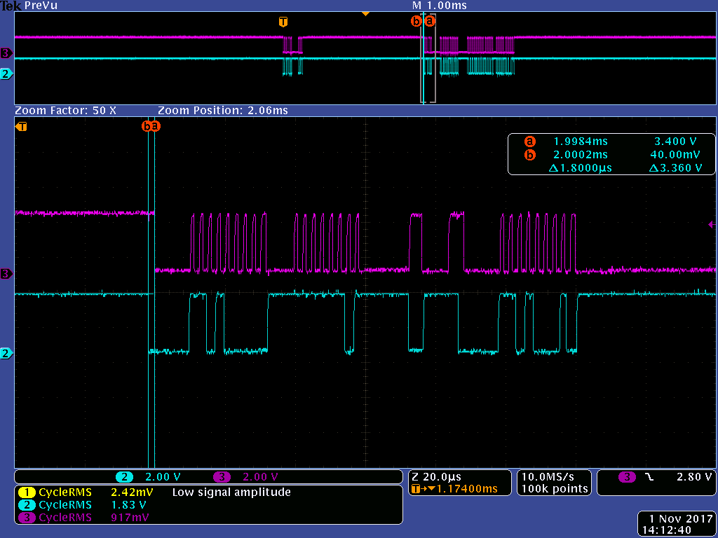
        I also compared waveform between using Fusion tool and our code, I found Fusion tool put delays between each byte, is this required by this chip. And we also found if we don't put delay between transmit and receive, sometimes communication will fail, please find below waveform from our code to read status.

    Please find attached our project file:

    UCD9090_Configuration_Rev-B.xml

    Thanks!

    Jack

  • This issue has been solved offline. the reason is that the MCU accidenlty sent out 0xD9 command to force device enter ROM mode. once device is under ROM mode, it stops responding normal PMBus commands.

    When launched fusion GUI, it automiatcally bring the device out of ROM mode temporarily to resume the normal functions. But when power cycle the device, it stays at ROM.

    Regards

    Yihe