This thread has been locked.

If you have a related question, please click the "Ask a related question" button in the top right corner. The newly created question will be automatically linked to this question.

TPS1H100-Q1: TPS1H100-Q1

Part Number: TPS1H100-Q1
Other Parts Discussed in Thread: TPS2660

I am connecting the TPS1H100 to a load that also has a large buffer cap of 470uF in parallel.

What can happen if the high voltage supply suddenly switches off and the buffercap is still charged so that a reverse current can flow through the body diode of the high side switch.

Will the device be able to detect reverse current since reverse polarity protection seems to work in a similar way.

Would I need to use an external diode in the output to block any reverse currents?

  • Hi Jan,

    The TPS1H100-Q1 does not have any reverse current blocking, despite its ability to handle reverse polarity events. An external diode would be needed to block reverse current.

    If you are looking for a high voltage device that can block reverse current, then perhaps the TPS2660 would work here. Do you think this device could work for your application?

    Thanks,

    Alek Kaknevicius

  • Alek,

    Here some more info I received.

    The TPS2660 has a too low current rating hence the choice for TPS1H100.

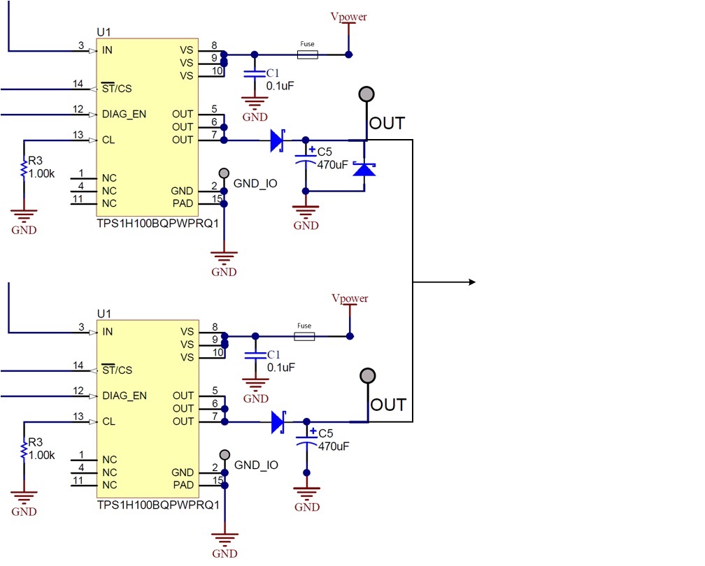
    The customer is placing two TPS1H100 in parallel.

    I think this might cause problems with the current sharing due to differences in RdsOn of the pass FET and voltage drops of the diodes in the outputs, see picture

    The enables are connected as well.

    What are your thoughts on this?

  • Hi Jan,

    There will be some current sharing differences between the two devices, but it should be limited to the variation in on-resistance for each of the devices. Either way, this is an effective method for increasing the current switched across the total solution. How much current would you like to put through the total solution?

    Thanks,

    Alek Kaknevicius

  • Alek,

    Total current is 3A
  • Hallo Alek, good morning/afternoon

    My name is Aishel. I'm the one who started this TPS1HQ1 discussion with Jan Volkering. The design that Jan showed above is something that i would like to use. Jan is on vacation at the moment (till July 10th), so i would like to continue this discussion with you if you don't mind.

    The total current is 4Amps and not 3 Amps.
    1) Do you have info about the RDS_on variation in production (or by design) from the TPS1H100 devices at 20 degrees ambient temperature?
    2) Do you have a LT_Spice model of that device that i can use for simulation.

    Thanks in advance for you time and information

    Greetings Aishel.
  • Hi Aishel,

    1) The datasheet shows the on-resistance variation at 25C, with a typical number at 80mΩ and a max number at 100mΩ. If the device stays at this temperature, then the worst case variation would be one device at 80mΩ and another device at 100mΩ. With 4A, the worst case is 1.78A through one channel and 2.22A through the other.

    2) We have several models available under the tools & software tab of the product folder: .

    Thanks,

    Alek Kaknevicius