This thread has been locked.

If you have a related question, please click the "Ask a related question" button in the top right corner. The newly created question will be automatically linked to this question.

LDC1612 oscillating at the incorrect frequency.

Other Parts Discussed in Thread: LDC1612, LDC1612EVM, TS3A24159

I am developing a product that incorporates the LDC1612 to monitor the inductance of a coil.  The coil itself doesn't meet the parameters to work with the LDC, so I am using it in series with a fixed inductor as per the instructions usually given on these forums.  The coil is approximately 0.3uH, and it is in series with a 4.7uH inductor at the moment.  The tank capacitor is 220pF.

When I use this setup on the LDC1612EVM, it works perfectly.  Trying it out on my prototype board, it is oscillating the tank system at ~615kHz, which is both the readout I get from the device and visually confirmed with my oscilloscope.  My settings for the LDC1612 are as follows:

//RCOUNT_CH1
0x09: 0x04D6);
//SETTLECOUNT_CH1
0x11: 0x002B);
//CLOCK_DIVIDERS_CH1
0x15: 0x1002);
//ERROR_CONFIG
0x19: 0x0000
//MUX_CONFIG
0x1B: 0x020F
//DRIVE_CURRENT_CH1
0x1F: 0x9000
//CONFIG
0x1A: 0x4001

The above only includes CH1, which is connected to the sensor in question.  CH0 is connected to a separate system that is working fine at this point, and uses similar settings.  I have 0x1A set to only read CH1 at the moment while I debug this part of the system.  The deglitch is set to 33MHz above, as I was trying out different deglitch settings.  I get the same results with ALL values for deglitch.

What could possibly be making this tank oscillate at 615kHz?  I can take the 0.3uH coil from my prototype board to the EVM and get the correct readings, but no matter what I do it always oscillates at this frequency.  I can't even begin to figure out what is happening so far.  Any help is greatly appreciated!

  • Hello Jtee,

    Please clarify what occurs when you remove the 0.3uH coil from the prototype and connect to the EVM - you said you get "correct readings"; what does that mean? What is the sensor signal amplitude? Please try measuring the scope with a 10k resistor between the INAx (or INBx) pin and the scope lead; I would like to ensure that no parasitic loading from the cap is affecting the measurement.

    Can you provide a scope shot of a few cycles of the sensor signal? Please be sure the amplitude range and timescales are clear.

    Regards,

    ChrisO
  • I will try to get you a scope shot tomorrow when I have everything available.

    By 'correct readings' I mean that the EVM correctly reads my circuit with a total inductance value of ~5.0uH - a 4.7uH in series with a 0.3 uH.  

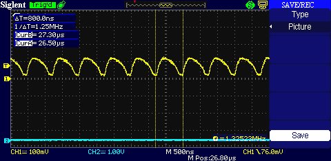
  • Here are some scope shots of the board.

    This is the signal at the IN1B pin of the LDC, before the series inductor.

    This is the signal after the series inductor.

    The actual sensor coil (~0.3uH) is located off of the board, attached to a screw terminal by two wires about 3 inches long.  This is the signal after the series inductor, at the screw terminal before the sensor coil.

    This is the signal after the sensor coil. The signal remains the same from this point back to the IN1A pin.

    I connected wires from IN1A and IN1B on my LDC1612EVM to the IN1A and IN1B pins on my prototype board and tested everything in-place.  This is the signal all throughout the system on the prototype board when driven and measured by the EVM.  Everything appears to be correct, although I think there is some parasitic capacitance that I have not accounted for changing the end values slightly.

    What could be causing this?  My initial thought is something to do with the drive current, although I haven't had any luck changing the settings on my prototype board.

  • I tried reading the drive current for CH1 to see what the automatic sensor amplitude correction was storing in the drive current register. It is storing 0x7C0, which is close to the 0x780 that the EVM settles in at when I connect it to my prototype board. I am completely stumped.
  • Hello Jtee,

    Please confirm that your sensor capacitor is in parallel with the series connection of two inductors. You cannot have the sensor capacitor across only the small inductor.

    Regards,

    ChrisO

  • Yes, the capacitor is in parallel with the series connection of the two inductors, just like in the diagram at this blog post: e2e.ti.com/.../inductive-sensing-how-to-use-a-tiny-2mm-pcb-inductor-as-a-sensor

  • Hi JTee,

    Are the scope traces you captured with respect to ground (i.e. INA to ground, NOT INA to INB)?

    With a 220pF sensor cap, you would need 66uH to have your observed 1.32MHz oscillation; that amount of inductance is well beyond your components. If your sensor cap was the incorrect value it would need to be around 3nF.

    Your signals, assuming they are ground referenced, do not look as expected. You can try increasing the sensor drive current to see if it helps - it is fine to configure the device to any setting; as you will not damage the LDC with any setting of the drive current.

    While I do not think this is the issue you are experiencing, it is recommended to use twisted pair for any extended runs.

    Could you post a picture of the sensor setup please?

    Thank you.

    Regards,

    ChrisO
  • All scope traces shown are taken with respect to ground.  My capacitor is definitely the correct value, 220pF, and the series inductor is definitely the correct value at ~4.7uH (give some wiggle room for part tolerances of course). 


    I will try increasing the drive current beyond what I already have and see what happens.  At this point I am fairly certain that it is a setting issue and not a sensor tank issue, once again as running leads from IN1A and IN1B of the LDC1612EVM to the IN1A and IN1B pins on my prototype board yield the expected results in the EVM GUI.

    I will post pictures as soon as I am able to.

  • Hello Jtee,
    were you able to resolve the issue and see the expected waveforms?
    For your information, expected waveforms when measured single-ended with a scope on the IN1A pin look like the screenshots in this blog: e2e.ti.com/.../inductive-sensing-how-to-configure-a-multichannel-ldc-system-part-2
  • Ben,


    So far I have not been able to resolve this issue.  I firmly believe it to be an issue with device settings at this point. I have now created a test board containing only a microcontroller, the LDC, basic power supply components, and my LC tank.  The same issue still persists, but once again the LC tank component works flawlessly when connected to an LDC1612EVM. 


    Chris,


    I tried adjusting the current in increments between the minimum and maximum allowed values, and saw no change in behavior.  At this time I have been refused permission to post photos of the prototype board due to trade secret concerns in the pre-market product. 

  • Hello JTee,

    Please set Config (address 0x1A) bits 12, 11, & 10 to 1, then repeat the changing of the current drive settings. While these would be recommended settings for the device, I don't think that this will resolve the issues you are seeing.

    Are there any other connections on the sensor to ground or some external circuit? Is it possible there is a large amount of parasitic capacitance between the sensor and some physical component?

    What is the power supply capacitive bypassing configuration you are using, and what is the LDC supply voltage?

    Regards,

    ChrisO
  • Hi JTee,


    Also, when you connected your sensor to the EVM, you said that you were getting the correct readings; can you compare the sensor frequency when the EVM drives your sensor to when your system drives the sensor?

    Regards,

    ChrisO

  • The oscillation frequencies (EVM compared to custom system) do not match.

    I observe the same behaviour as JTee and have verified all which was mentioned in this thread before. My LC tank is 100 pF parallel to 55 µH. The EVM gives a realistic value for L; my system reads about 290 µH. The oscillation frequency measured in my system is roughly 900 kHz, at the EVM it is 2 MHz.

    I set the EVM to the same settings as in my application. The EVM works fine with these.While applying the settings to the EVM, I noticed two things:

    - The Input and Reference Divider Settings are set to 0 in the EVM by default. The LDC1612 datasheet states that "0" was reserved and should not be used.
    - There is a Register called "System Clock Divider", Address 0x1D, which is not documented in the LDC1612 datasheet. The System Clock Divider is set to 2 by Default (register value 0x0200).

    Changing these divider settings in my application did not help; so the EVM and my custom LDC application now run on the same settings, but read different inductance values.

    When using a much larger capacitor value (4700 pF), the inductance reading in my system is "correct" (55 µH, as per design), and the EVM reads 48 µH.

  • Hello Torben,

    it appears both your firmware and GUI is out of date. The default divider setting should be correct in the latest firmware: LDC1612EVM Firmware. The latest GUI has an improved user interface and also doesn't show the unsupported sysclk divider (which should never be changed from its default of 2): Sensing Solutions EVM GUI Tool v1.8.8 (Rev. A)

    To get a correct inductance reading, please ensure that the 'Parallel Capacitance' matches the capacitor that you have on the PCB (configuration > Sensor properties and input adjustments > sensor filter bank).

    Please let me know if you still have any issues after upgrading GUI and firmware.

  • Hello Ben,

    Thanks for your reply. I have updated the EVM Firmware and checked the hardware and software configuration in the new GUI. The parallel capacitor value matches the capacitor which I have on my board. The GUI shows an oscillation frequency of 2.1 MHz, which is as calculated (100 pF, 57 µH). I can measure this frequency with my scope, too.

    With the "larger" tank (4700 pF, 57 µH) attached, the inductance and frequency values shown in the GUI do not match the measurements with my scope or my custom system (EVM GUI reads 345 kHz, scope/custom systems read 331 kHz). Also, the GUI reading is very noisy (the value quickly changes about 5 kHz), while the signal observed on the scope is steady. This might be a glitch issue (deglitch filter set to 1 MHz), which is why I wanted to try a "smaller" tank capacitor (100 pF) in the first place.

    I think I have just stumbled upon the cause for the deviations in the 100 pF case. I am using an analog switch (TS3A24159) between the LDC and the LC tank. Applications with a multiplexer are possible (as seen here). Unfortunately, the TS3A24159 has a C_ON of 224 pF at NC/NO and an additional 250 pF at COM. With 100 pF on the LC tank, this makes 600 pF; calculating with 600 pF instead of 100 pF results in much better inductance values. When I use 4700 pF at the LC tank, the capacitances of the analog multiplexer are almost neglectable. The MUX proposed in the TI Reference design is a Special High-Speed USB Multiplexer with a much lower capacitance value (7.5 pF). I will give it a try with a "better" multiplexer.

    Is the LDC1612 more prone to glitches at lower oscillation frequencies?

  • Well I have resolved the issue, and it turned out to be a pretty simple oversight.  I was attempting to isolate my coil using two transistors during measurement, and didn't realize that they had a built-in body diode that conducted a small current.  I replaced these transistors with SCRs and everything is working exactly as expected.  

    The reason I was getting correct measurements with the EVM and not in-circuit is that I did not have the EVM ground joined to the ground of my circuit.  I tested this by connecting the EVM to my old circuit and joining the grounds, which replicated the problem on the EVM.  

  • Hi Jtee,
    I am glad you managed to solve the issue. Thank you for sharing your solution.