This thread has been locked.

If you have a related question, please click the "Ask a related question" button in the top right corner. The newly created question will be automatically linked to this question.

IWR1642BOOST: People Counting Lab command recognization error

Part Number: IWR1642BOOST
Other Parts Discussed in Thread: IWR6843, IWR1642

Hello,

I have IWR1642BOOST evaluation module from TI and trying to run "people counting lab"  which is available on mmWave Industrial Toolbox 4.1.0.

For this purpose,

1) I set the device to flashing mode (SOP[2:0]=101) and program it using xwr16xx_pcount_lab.bin file via Uniflash software.

2) I set the device to functional mode (SOP[2:0]=001) and run pplcount_gui.exe file

3) I choose the pins, click the connect button, and check the connection is successful. 

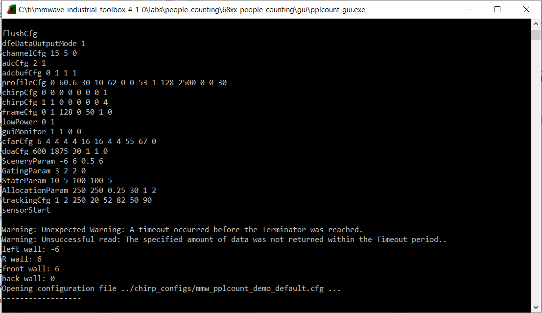
4) Then I start the device and get the error messages as below;

Warning: Unexpected Warning: A timeout occured before the Terminator was reached.
Warning: Unsuccessful read: The specified amount of data was not returned within the Timeout period.

In order to solve the problem, I check the following steps;

i) Is the ".bin" file loaded correctly?

ii) Are SOP connections correct?

iii) Are right COM ports chosen? Does any other software use same COM ports, etc?

I flashed the board with the IWR1642 binaries and use the gui from IWR1642 version of the people counting lab. But, for IWR1642 version of the lab, both gui and code do not work correctly. When I run it, I got the error as below.

Therefore, I have tried to fix this problem and I found this thread on the forum (see url). On the thread, Justin says, the people counting gui can be swapped between IWR642 and IWR6843. So, I have used gui from the IWR6843 version of the people counting lab.

https://e2e.ti.com/support/sensors/f/1023/p/795831/2944877?tisearch=e2e-sitesearch&keymatch=iwr1642boost%25252520warning#2944877

When I run gui from the IWR6843, I got the error again.

I can not manage to operate the  device correctly. I need your help to get rid of this problem. Thank you in advance.

Best regards,

Melek

  • Hi Melek,

    We have a new python based gui that does not have this issue - this appears to be a conflict with the COM port drivers and the Matlab runtime environment. Please use the gui included in the 3D People Counting lab.  Instructions for use are included in the 3D People Counting user's guide. Before clicking connect, make sure to select "(Legacy) 2D People Counting".

    Regards,

    Justin

  • Hi Justin,

    Thank you in advice. 

    I flashed the board with the IWR1642 binaries and i used the gui in the 3D People Counting lab with (Legacy) 2D People Counting configuration type. I downloaded chirp configuration for the IWR1642 on the chirp configuration page and select it on the gui. When i click the send configuration to configure the device and start tracking, there is no change on the gui.

    Why can't i operate the device?

    Best regards,

    Melek

  • Hi Melek,

    So it seems like with both GUIs that the device won't properly start. A few things to check:

    1. Does the device work with the OOB demo?
    2. What version is the device? ES1 and ES2 devices require different firmware, and will not work with the wrong firmware. See the device errata. ES2 devices say 502AC, and ES1 devices say 502.
    3. Get a version of the toolbox that works with the correct ES.
    4. If the board still does not work, after sending a configuration using the gui, close the gui completely and open a utility like tera term to monitor the data comport. If the device is working properly,, you will see random values coming across the COM Port.

    Regards,

    Justin

  • Hi Justin,

    I checked the things above. All of them seem right.

    1. Yes, the device worked correctly with mmWave Demo Visualizer and i saw the data stream.
    2. Version of the my device is ES2.0 silicon. It says 502AC on the chip.
    3. It says that version of the toolbox must be greater than 2.0.1 for ES2.0 device in the people counting user’s guide. I worked with mmwave industrial toolbox 4.1.0. So, it seems right.

    The device worked properly with 5V 2A adapter when i started mmWave Demo Visualizer. Therefore, i didn't think there would be a problem with the adapter. I solved my problem by changing the 5V 3A powered adapter instead of 5V 2A adapter. 

    Thank you for your help.

    Melek