


Other Parts Discussed in Thread: TPS62177, AFE031, LM5165,
Hello,
my problem is that the User Guide don't give enough information about the DC-Bus coupling.
It is referencing on page 16 on the design of tidu167 where I was told that the design is too old and had been taken down and I should look for TIDA-060001but that is more focused on the AC coupling. Furthermore I noticed on page 19 Figure 26 a mistake that the schottky and zener diode have the same schematic symbol which will confuse the user. It would be great if the figure and the schematic get fixed.
I would like to communicate over a 48V DC-Bus where a max amperege of 3A can exist. I would like to communicate in the Cenelec C Band with the main frequency of 131,25 Khz.
I tried to make an schematic for the plc communication but there are some points where I can't find any information about it.
Here is a picture of the schematic which I made. I marked some components where I didn't find anything or I am unsure if I chosed the right parameter.
Also do I need a HV Capacitor (C4) with a higher Voltage rating (48V+ amplified signal) ?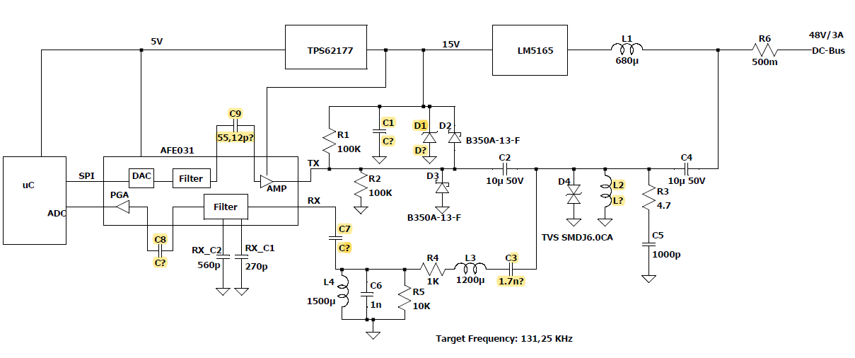
Greetings Patrick


