This thread has been locked.

If you have a related question, please click the "Ask a related question" button in the top right corner. The newly created question will be automatically linked to this question.

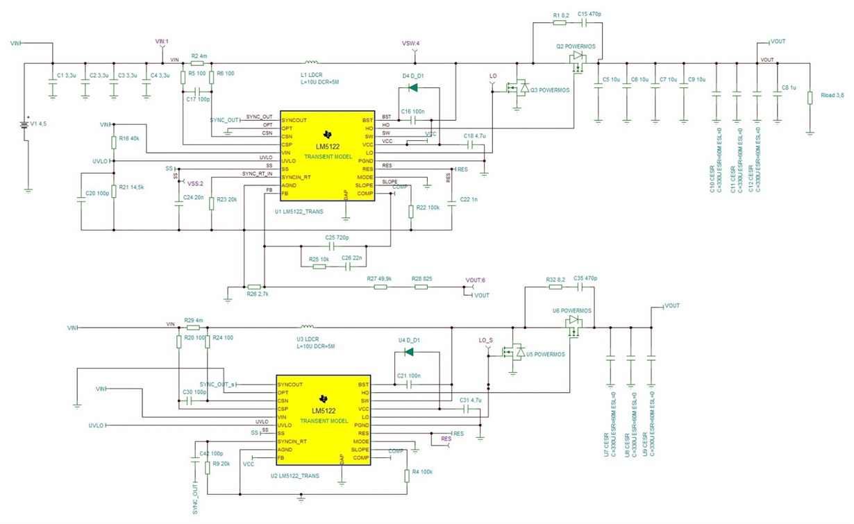
WEBENCH® Tools/LM5122: We tried TINA-TI for the simulation of this Dual-Phase LM5122 schematic with some minor component value-changes. But the simulation is not going well... who can help us ?

Part Number: LM5122
Other Parts Discussed in Thread: TINA-TI

Tool/software: WEBENCH® Design Tools

Dear Forum-reader,

We try with the LM5122 in Dual-phase design ( Design = originally from the TI - site ) to convert an Input voltage (3 - 4,5Vdc / 50Amp) to an Output voltage of 24Vdc.

We changed R21 (for setting the UVLO-Pin of LM5122 for lower input voltage). (We used the formulas in the LM5122 pdf document)

Input Voltage:4,5V is minimum start-up voltage ... and we want it to work to as low as 3V (or 3,5 - 4V)  if possible with a continuous amount of current (max 50A continuously).

The output voltage is already set to 24Vdc. (with R26, R27, R28).

We changed the filter between the Comp- and FB-Pin (R25, C25, C26).  (We used the formulas in the LM5122 pdf document)

We changed the Input source to a battery (settings: 4,5V and tried it also with 5V)

WE USED   =NOT=  Webench simulation tool  =  BUT : TINA-TI Simulation tool for the schematic below. 


Questions: 

1) Is it possible to change the simulation speed ? (it takes about 1 to 2 hours)

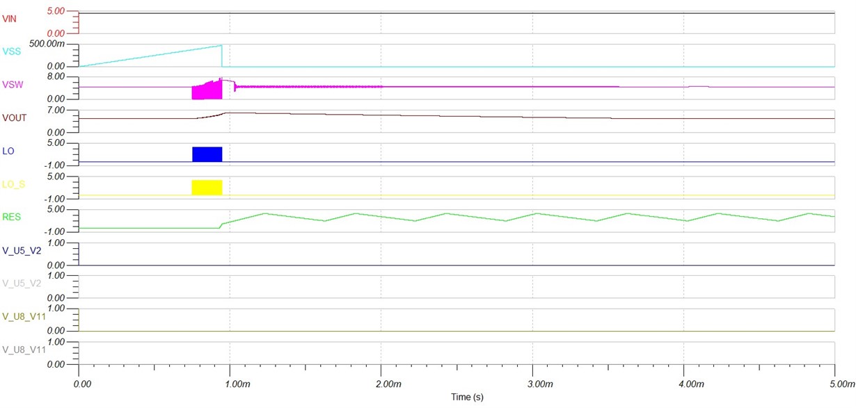
2)  If we look at the simulation values, the Vout is not reaching 24Volts.

=> Is there something we do wrong ?

3) If we look at the simulation values, the LO and LO_S Fet switching gate signals stop before the 1ms... strange.

=> How and why does this happen ?  

Who can help us out with these questions ?

Thank you for your time,

Anthony and Heba.

  • Hi Anthony,

    Thanks for showing interest in LM5122. I'll move this to the relevant team who can help you with TINA simulations.

    Regards,

    Vishwanath 

  • Hi Anthony,

    Thanks for submitting this question. Can you attach your TINA-TI file so I can take a look?

    Thanks,

    Richard

  • Hi Richard,

    Thank you for your help!

    I will attach the TINA-TI file (from my girlfriend Heba).

    Hopefully you can find something.

    Thank you very much.

    Question:  I know that the LM5122 can start-up with a VIN of 4,5Vdc  …

    but is there a possibility if we have only a VIN of 3Vdc - 3,5Vdc ...

    (maybe an additional circuit to get the 4,5V start-up for the LM5122) ?

    Kind regards,

    Anthony vd Vegt

    dualphase(heba)v 6.TSC

  • Hi Richard, 


    Did you receive the Tina-ti file ? 


    And if so, can you tell us already something about the

    Simulation and the question ?


    Thank you very much for your help and time.

    Have a nice weekend. 


    Anthony 


  • Hi Anthony,

    Sorry for the delayed response. I haven't had time yet to open up the TINA-TI file, but I have received it. Regarding your other question, you can use the output to supply the bias pin of the LM5122 so you can lower your input voltage after initial startup.

    Thanks,

    Richard

  • Hi Richard,

    No problem.  Thank you very much for your reply and short answer to my question.

    => (Can you give an example of using Vout to supply the bias pin UVLO … When starting-up... and … after start-up of the LM5122)

    => Hopefully you can analyse / check the TINA-TI simulation file before the 15th of June.  (my girlfriend has to complete /finish and send inn her documentation to her teacher )

    Please no stress.  Thank you for your help.

    Nice to hear from you again and if you can tell us more about the simulation / and question, that would be great.

    Anthony

  • Hi Anthony,

    Sorry for the delay.

    Please see the attached image:

    During the startup, the input supply will power the VIN_pin, but afterwards, when the input has been boosted to the output, the diode connecting the output to the VIN_pin will become forward-biased, and the diode connecting the input to the VIN_pin will become reversed bias since the cathode voltage is higher than the anode. This way, your input supply can drop lower after the output has hit the regulation target. 

    Unfortunately, I'm unable to carefully check your TINA-TI simulation before the 15th of June, there was a lot of delay piled up. One thing I've noticed, is that this test bench is specified for 9V, and from previous experience I've had with this- the model is built with that input condition in mind- this may explain why you are getting incorrect simulation results. 

    Let me know if this helps,

    Richard