This thread has been locked.

If you have a related question, please click the "Ask a related question" button in the top right corner. The newly created question will be automatically linked to this question.

CC1352R: High sub-1GHz noise floor

Part Number: CC1352R

Hello,

first a disclaimer: I am an amateur, and only do this for personal projects and as a learning experience. This means I am not looking for absolute best performance or compliance, and that I don't have access to specialized equipment (ie, I don't have a signal generator!)

I designed a custom board, a lot of which is based on the Launchpad. The most important differences are that it uses Johanson baluns and two antennas (antenna 2 and antenna 6 from the antenna DK 2 kit) 

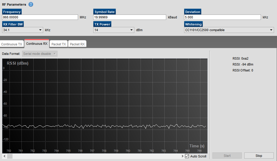
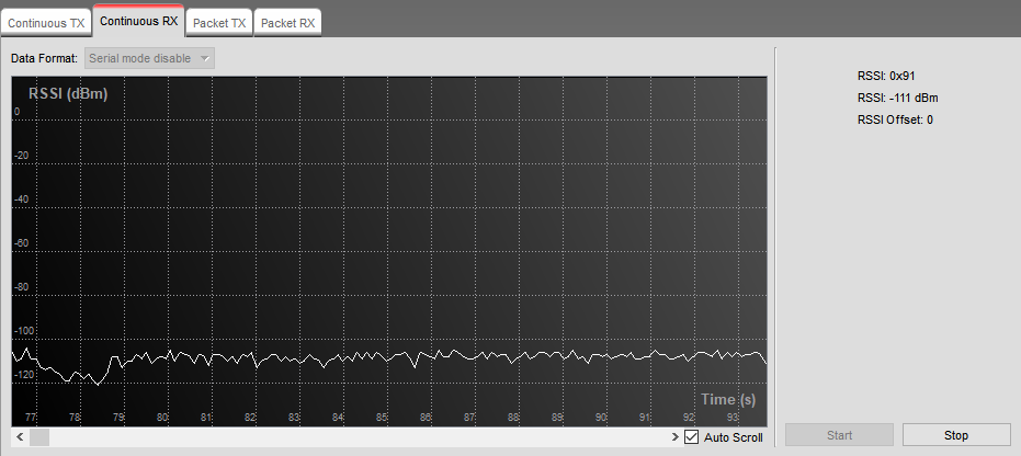
Everything seems to check out with the board except that the noise floor on sub-1GHz is really high (launchpad is at expected ~-110dBm):

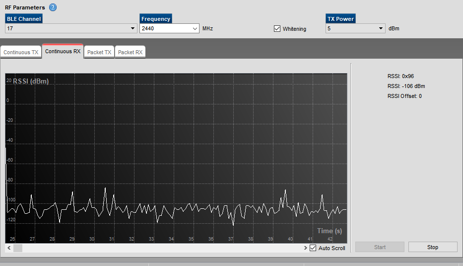
It seems OK at 2.4GHz:

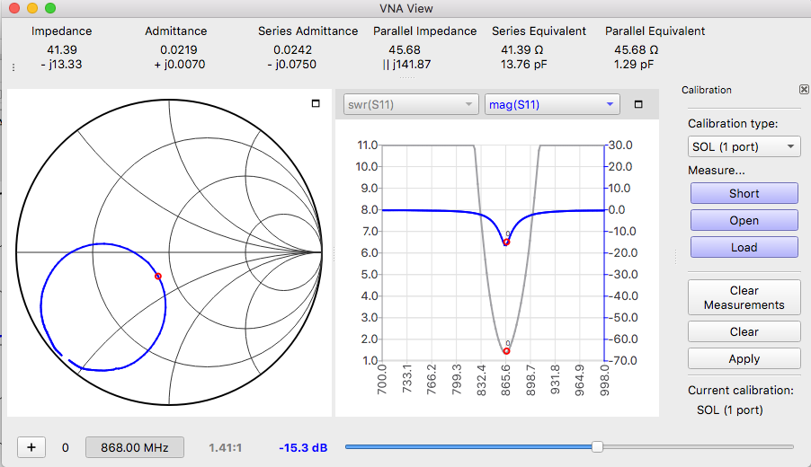
The antenna is well-matched (at least according to my cheap VNA):

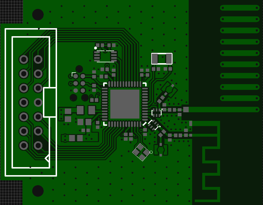
4-layer board (same stack up as Launchpad) top layout. I was careful with power and antenna sections (at least, I think so!):

Since I can't do conducted performance tests, what are my next options, if any? I haven't done range tests yet, so this may not be a huge issue in my case, but  any advice is very much appreciated!

  • Do you have any antennas that you can connect to the JSC connector (disconnect the PCB antenna) and compare the noise level?

    You will take a hit on range since the noisefloor is 20 dB higher than the LP and it's a 2x in range for every 6 dB.

    Not sure if it will impact since it's short but the short trace up to the JSC will be stub even when this is not in use. It could also be that you used the wrong reference point for the antenna matching etc.
  • Hi TER, yes I will test with antenna 6 from the TI antenna kit later this week-end. Thanks for the suggestion.

    I'm not sure what you mean as far as the wrong reference point for the match? I've set it to 868, and at that frequency, at least according to my readings, I have a better match than antenna 6 (which looks like a compromise for a broader range).

    I have been wondering about the stubs, but can't think of a way to measure/remove them from the rquation! How's that normally done?

  • Stubs: You can try to cut it. Ideally you should have made the PCB without it.

    VNA reference point: When you measure with a VNA and doing matching you have to me careful on how you measure, see chapter 6 in www.ti.com/.../swra161b.pdf
  • Cool, I'll cut the trace to the tx line.

    For measurements, thanks for the reference. I was as careful as I could be; was using the jsc connectors and cable from antenna kit to calibrate and measure. Wouls it have been better not to have connectors and to solder the cable, as in the application note? In other word, is my measuring technique hrowing off the results significantly?
  • If you used the JSC connector you could easily have used the wrong reference point. Following the appnote increase the probability for getting it right.

    But if you have the antenna kit, have you tried to attach on of the antennas from the kit to the JSC and checked the noisefloor?
  • TER said:
    If you used the JSC connector you could easily have used the wrong reference point. Following the appnote increase the probability for getting it right.

    But if you have the antenna kit, have you tried to attach on of the antennas from the kit to the JSC and checked the noisefloor?

    Hi TER, update #1: don't think it was the stub. Cut the trace close to the balun, no difference.

    I will test antenna 6 from the kit on another board; just gotta unsolder the series cap and measure. Will post back.

  • I assume that trying another antenna is to determine whether it is the board that is noisy; instead of desoldering it, I tested trying to block the antenna signal and managed to bring the noise floor to less than -110 dBm (avg -120). Can conclusions be drawn from this? Is the antenna picking up so much noise because it's mismatched or are there other factors to consider?
  • TER, DK2 antenna 6 works better. Just not sure what the next steps are as far as my antenna. I used the same dimensions as www.ti.com/.../swra416.pdf so not too sure what to do next. 

  • Then you haven't succeeded matching your antenna correctly. The required match will be a function of both the size of the ground plane on the PCB and casing.