This thread has been locked.

If you have a related question, please click the "Ask a related question" button in the top right corner. The newly created question will be automatically linked to this question.

@Ryan Lin : LMX9838 for KC approval ( KOREA CERTIFICATION)

Other Parts Discussed in Thread: LMX9838-SW

Hello.

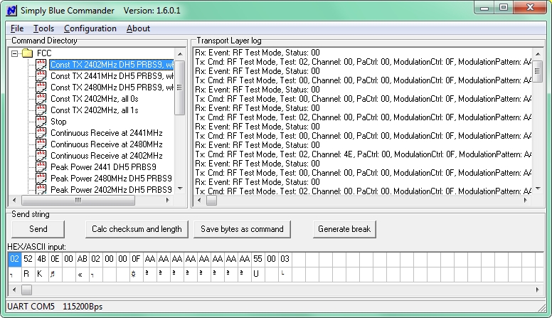
This is to request a test jig and software for LMX9838 Bluetooth Serial Port Module.

We are trying to get KC approval in Korea but we do not have the appropriate tools for RF test.

What we need to do for test is as below.

- product has to send signals continuously
- channel can be changed (low, middle, high)
- RX mode
- rated power change (-10%, rated, +10%)
- hopping mode


Do we need a test jig and software?
Please support how to do a RF test.

  • Hi Daesung,

    All are possible except changing the output power. This device has output power.

    Have you used the LMX9838DONGLE before?

    Thanks,

    Julian

    snwc002.zip

  • Dear Julian,

    Thank you very much for your information.
    It seems your dongle is how we call a test zig board.

    Could you let me know how to receive the sample?
    1pc is enough for RF testing.
  • The regular LMX9838DONGLE is for sale on ti.com

    Do you need to remove the antenna from the IC for testing?

    Thanks,

    Julian

  • Dear Julian,

    I have received LMX9838DONGLE by purchasing from this website.

    But I am still not sure how to do RF test with your documentation. The RF test we need to is similar to FCC.

    The test sample is required these conditions :
    1. The sample can send signal continously
    2. Channel can be changed (low, mid, high)
    3. RX mode
    4. power can be changed as -10% of rated, rated, +10% of rated.
    5. Hopping mode

    Could you let me know how to do RF test?

    For the referece, I attached the FCC test report.

    Also, we needs some documents.
    1. circuit diagram
    2. parts layout or PCB layout
    3. block diagram
    4. antenna specification

    Your support will be truly appreciated.

    Thanks.

    TI LMX9838 FCC test report.pdf

  • Hi Daesung,

    Please e-mail me for a response on the conditions 1-5. (4) Our device has fixed output power so this is not possible.

    Will this test require conducted testing? Testing without the integrated antenna in the LMX9838 device and with external antenna?

    1) circuit schematic is included in the files you downloaded check.
    2) I will check if I can get access to this
    3) I will send it to you via e-mail
    4) looking into this.

    Please e-mail me to: j-dimatteo@ti.com

    Thanks,
    Julian
  • Dear Julian,

    I relied to your email many times but I have not received any news from you since 12th August. So I am writing here as well. Could you update the status for shipping?

    Please understand my frequent asking for your support. My customer has waited so long.

    Please update.

    Thanks.

  • Hi Daesung,

    I replied to your e-mail a few days ago. Please feel free to reach out if you need anything else.

    Thanks,
    Julian
  • Hi Daesung,

    We have come to find out that one of the files within the LMX9838-sw is corrupt. I'm talking about the zip file that you get when you click here:

    For example, when you try the SBC_FCC.dir tests shown below, you would not be able to put the LMX9838 into a continuous transmit mode:

    I have attached the corrected file below:

    SBC_FCC.DIR

    Please replace the existing SBC_FCC.dir file from within the zip file, with the new file attached above.

    Here is the description of what was wrong with the original file (which showed no reactions when "Send" was clicked) and how to correct it:

    "The reason you do not see any reaction from the module is the command sent is incorrect.

    You send:


    In LMX9838 Software User Guide (AN1699) chapter 7 a command frame is shown in 7.1 and the detailed description of the RF_TEST_MODE command is presented on page 173.

    The string sent is 02,52,4B,0D,00,AA… The bytes marked yellow are defining data length which is always 14 so there must be 0E,00 instead. The module answers “RF Test Mode, Status: 01”. In table 298 (page 181) you may find status codes and 0x01 is “ERROR_INVALID_NO_OF_PARAMETERS The number of bytes in the request does not correspond to the protocol specification”.

     If “Interpret traffic” is selected, SB Commander (Simply Blue Commander) will show raw bytes only if the command structure is incorrect.

    An example of correct behaviour:

     I checked the SBC_FCC.DIR file that is distributed inside snwc002.zip you may download from ti.com and it is incorrect. The corrected file is attached above.

    Anyhow the user shall read the software guide parts to be able to modify the command parameters.

     The important thing for the RF_TEST_MODE  command is it will activate the RF test mode. To exit the test mode, a reset of the device must be performed. The transmitter test must be stopped before a new test with changed parameters can be started."


    Hope this helps. Please try the new file I've attached above and let me know if your issue is resolved or not?


    Regards,

    Hooman