This thread has been locked.

If you have a related question, please click the "Ask a related question" button in the top right corner. The newly created question will be automatically linked to this question.

Using ADC with cc2650 Sensortag and Devpack Debugger

Other Parts Discussed in Thread: CC2650STK

Hi,

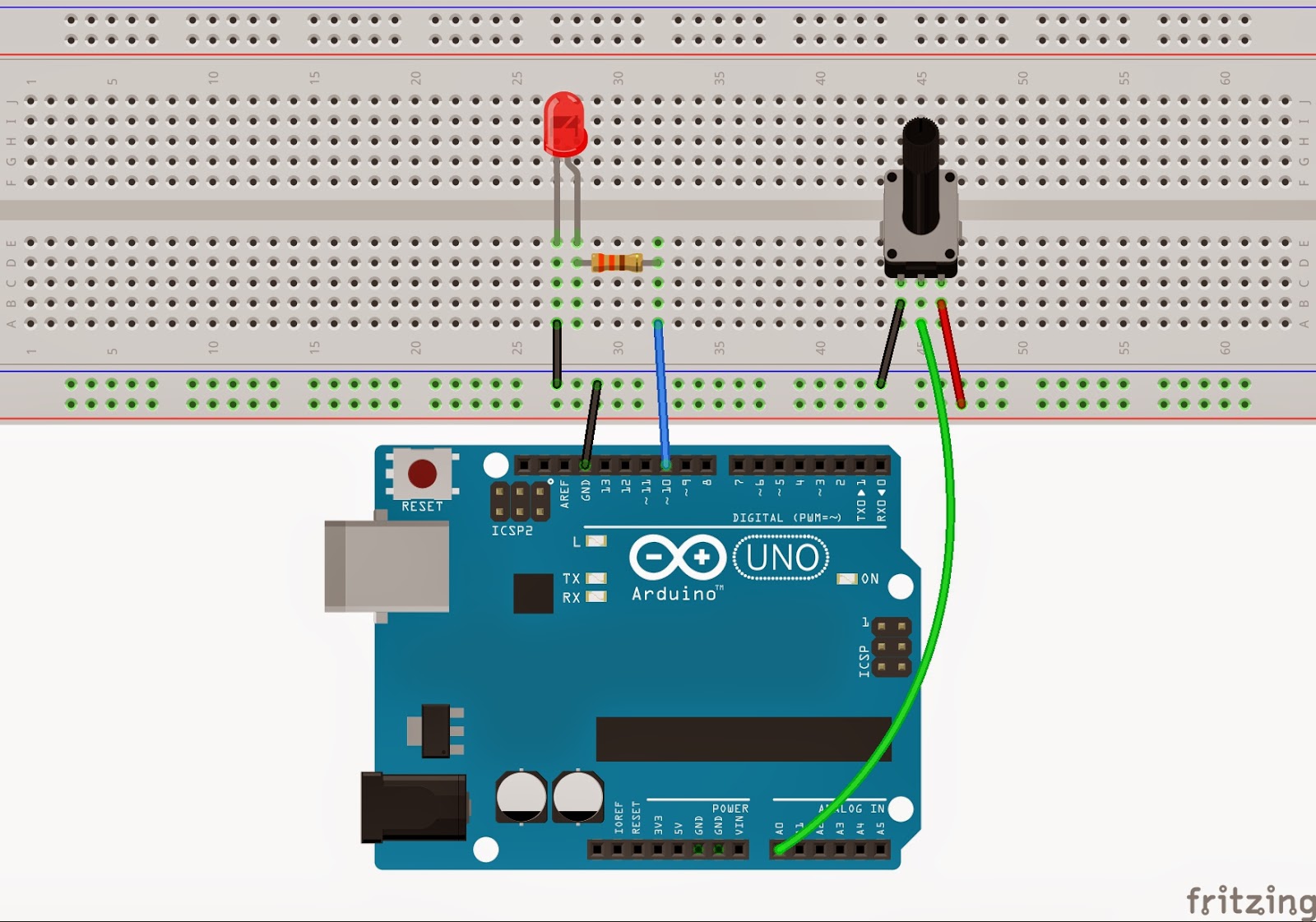
1-)I try to leran how to use adc pins on sensortag so i want to do  adjust brightness of LEDs with potentiometer. How can i do this? I viewed this example but its complicated for me. Can you show simple example about it? https://e2e.ti.com/support/wireless_connectivity/bluetooth_low_energy/f/538/p/404426/1433112#1433112

2-)Can you recommand any source about using adc functions, semaphores and hwi on CCS ? 

Thanks..

  • Don't understand what do you mean "using adc pins on sensortag so i want to do adjust brightness of LEDs with potentiometer"? Can you elaborate?
  • I mean i want to control brightness of a led with using adc pins(DP0-DP3). The resistance is increased by potentiometer, brightness of led will decrease so i have to use adc pins ? Am i wrong?
  • can you provide a diagram of your design so we can better assist you?
  • If I understand correct, you would need to use one pin as ADC to read voltage change and use another pin (maybe LED pin) to output PWM signal according to the input of ADC pin. Is my understanding correct?
  • Yes you are correct Chen. Arduiono example is here maybe it provides to understand me better; 2.bp.blogspot.com/.../PotIleLedParlakligi_bb.jpg
  • I would suggest you to separate this into two parts. First, make sure you can read ADC correctly from for example DP2 on CC-DEVPACK-DEBUGGER. Second, try to implement PWM output. After you build those two successfully, you can combine them together.
  • Im trying to read ADC but im confused. I have to use semaphore or hwi to read ADC? I cant understand how the mechanism works exactly?
  • Yes, it uses semaphore and hwi to read ADC in svend's sample code. When it triggers ADC sample, it would wait for semaphore until ADC sampling finish and ISR post the semaphore to complete sampling.
  • Ok i got it thanks for helps.

    I have a new problem. What is that means? I can build svend's example but while debuging ,it gives this errror;

    ysbios.knl.Task: line 505: assertion failure: A_badTimeout: Can't sleep FOREVER.
    xdc.runtime.Error.raise: terminating execution
  • I use UART to dump ADC reading and don't use debug function in IDE. Maybe I can test debugging with IDE to see if I see similar issue.
  • You are welcome.
  • /* XDCtools Header files */
    #include <xdc/std.h>
    #include <xdc/runtime/System.h>
    
    #include <ti/sysbios/knl/Semaphore.h>
    #include <ti/sysbios/knl/Clock.h>
    #include <ti/sysbios/family/arm/m3/Hwi.h>
    #include <ti/sysbios/family/arm/cc26xx/Power.h>
    
    /* BIOS Header files */
    #include <ti/sysbios/BIOS.h>
    #include <ti/sysbios/knl/Task.h>
    
    /* TI-RTOS Header files */
    #include <ti/drivers/PIN.h>
    #include <ti/drivers/pin/PINCC26XX.h>
    #include <ti/drivers/Power.h>
    #include <ti/drivers/power/PowerCC26XX.h>
    #include <ti/drivers/UART.h>
    // #include <ti/drivers/Watchdog.h>
    
    #include <driverlib/aux_adc.h>
    #include <driverlib/aux_wuc.h>
    #include <inc/hw_aux_evctl.h>
    
    /* Board Header files */
    #include "Board.h"
    
    #define TASK_STACK_SIZE 512
    #define TASK_PRI        1
    
    
    char taskStack[TASK_STACK_SIZE];
    Task_Struct taskStruct;
    
    
    #define SAMPLECOUNT 20
    #define SAMPLETYPE uint16_t
    #define SAMPLESIZE sizeof(SAMPLETYPE)
    
    #define ALS_POWER   IOID_26
    #define ALS_OUTPUT  IOID_23
    
    SAMPLETYPE adcSamples[SAMPLECOUNT];
    SAMPLETYPE singleSample;
    
    // Analog light sensor pins
    const PIN_Config alsPins[] = {
    		ALS_POWER       | PIN_GPIO_OUTPUT_EN | PIN_GPIO_HIGH   | PIN_PUSHPULL | PIN_DRVSTR_MAX,
    		ALS_OUTPUT      | PIN_INPUT_DIS | PIN_GPIO_OUTPUT_DIS ,
    		PIN_TERMINATE
    };
    
    PIN_Handle pinHandle;
    PIN_State  pinState;
    
    void taskFxn(UArg a0, UArg a1);
    
    int main(void) {
    
    	//Initialize pins, turn on GPIO module
    	PIN_init(BoardGpioInitTable);
    
    	//Initialize task
    	Task_Params params;
    	Task_Params_init(&params);
    	params.priority = TASK_PRI;
    	params.stackSize = TASK_STACK_SIZE;
    	params.stack = taskStack;
    
    	Task_construct(&taskStruct, taskFxn, &params, NULL);
    
    	BIOS_start();
    }
    
    void taskFxn(UArg a0, UArg a1) {
    
    	// Set up pins
    	pinHandle = PIN_open(&pinState, alsPins);
    
    	// Enable clock for ADC digital and analog interface (not currently enabled in driver)
    	AUXWUCClockEnable(AUX_WUC_MODCLKEN0_ANAIF_M|AUX_WUC_MODCLKEN0_AUX_ADI4_M);
    	// Connect AUX IO7 (DIO23) as analog input. Light sensor on SmartRF06EB
    	AUXADCSelectInput(ADC_COMPB_IN_AUXIO7);
    
    
    	// Set up ADC
    	AUXADCEnableSync(AUXADC_REF_FIXED, AUXADC_SAMPLE_TIME_2P7_US, AUXADC_TRIGGER_MANUAL);
    
    	// Disallow STANDBY mode while using the ADC.
    	Power_setConstraint(PowerCC26XX_SB_DISALLOW);
    
    	uint8_t currentSample = 0;
    
    	while(currentSample < SAMPLECOUNT) {
    
    		//Sleep 100ms in IDLE mode
    		Task_sleep(100 * 1000 / Clock_tickPeriod);
    
    		// Trigger ADC sampling
    		AUXADCGenManualTrigger();
    		singleSample=AUXADCReadFifo();
    
    		adcSamples[currentSample++] = singleSample;
    
    	}
    
    	// Disable ADC
    	AUXADCDisable();
    	// Allow STANDBY mode again
    	Power_releaseConstraint(PowerCC26XX_SB_DISALLOW);
    
    	// Restore pins to values in BoardGpioTable
    	PIN_close(pinHandle);
    }

    I modified svend's code like this but doesnt works. Why?

    Thanks..
  • I see you remove semaphore. You might need to add a sleep in between "AUXADCGenManualTrigger()" and "singleSample=AUXADCReadFifo()" like the followings:

    AUXADCGenManualTrigger();
    Task_sleep(100 * 1000 / Clock_tickPeriod);
    singleSample=AUXADCReadFifo();
  • Hi,

    I can read ADC values from potentiometer but it gives wrong value. Always it shows values that are between 0 - 3900ohm. I tried different pot.(10k and 1k) but nothing changes. If i change the AUXADC_REF_VDDS_REL to AUXADC_REF_FIXED, it shows  between 0-3100ohm . Why?  

    Here is my code 

    /* XDCtools Header files */
    #include <xdc/std.h>
    #include <xdc/runtime/System.h>
    
    #include <ti/sysbios/knl/Semaphore.h>
    #include <ti/sysbios/knl/Clock.h>
    #include <ti/sysbios/family/arm/m3/Hwi.h>
    #include <ti/sysbios/family/arm/cc26xx/Power.h>
    
    /* BIOS Header files */
    #include <ti/sysbios/BIOS.h>
    #include <ti/sysbios/knl/Task.h>
    
    /* TI-RTOS Header files */
    #include <ti/drivers/PIN.h>
    #include <ti/drivers/pin/PINCC26XX.h>
    #include <ti/drivers/Power.h>
    #include <ti/drivers/power/PowerCC26XX.h>
    #include <ti/drivers/UART.h>
    
    #include <driverlib/aux_adc.h>
    #include <driverlib/aux_wuc.h>
    #include <inc/hw_aux_evctl.h>
    
    /* Board Header files */
    #include "Board.h"
    
    #define TASK_STACK_SIZE 512
    #define TASK_PRI        1
    
    char taskStack[TASK_STACK_SIZE];
    Task_Struct taskStruct;
    
    Semaphore_Struct sem;
    Semaphore_Handle hSem;
    
    #define SAMPLETYPE uint16_t
    
    #define ALS_POWER   IOID_26
    #define ALS_OUTPUT  IOID_27
    
    SAMPLETYPE singleSample;
    // Analog light sensor pins
    const PIN_Config alsPins[] = {
    		ALS_POWER       | PIN_GPIO_OUTPUT_EN | PIN_GPIO_HIGH   | PIN_PUSHPULL | PIN_DRVSTR_MAX,
    		ALS_OUTPUT      | PIN_INPUT_DIS | PIN_GPIO_OUTPUT_DIS ,
    		PIN_TERMINATE
    };
    
    PIN_Handle pinHandle;
    PIN_State  pinState;
    
    //UART_Handle uHandle;
    
    void taskFxn(UArg a0, UArg a1);
    
    int main(void) {
    
    	//Initialize pins, turn on GPIO module
    	PIN_init(BoardGpioInitTable);
    
    	//Initialize task
    	Task_Params params;
    	Task_Params_init(&params);
    	params.priority = TASK_PRI;
    	params.stackSize = TASK_STACK_SIZE;
    	params.stack = taskStack;
    
    	Task_construct(&taskStruct, taskFxn, &params, NULL);
    
    	BIOS_start();
    }
    
    void taskFxn(UArg a0, UArg a1) {
    
    
    	Semaphore_Params sParams;
    	Semaphore_Params_init(&sParams);
    	sParams.mode = Semaphore_Mode_BINARY;
    
    	Semaphore_construct(&sem, 0, &sParams);
    	hSem = Semaphore_handle(&sem);
    	// Set up pins
    	pinHandle = PIN_open(&pinState, alsPins);
    
    	// Enable clock for ADC digital and analog interface (not currently enabled in driver)
    	AUXWUCClockEnable(AUX_WUC_MODCLKEN0_ANAIF_M|AUX_WUC_MODCLKEN0_AUX_ADI4_M);
    	// Connect AUX IO3 (DIO27) as analog input. Light sensor on SmartRF06EB
    	AUXADCSelectInput(ADC_COMPB_IN_AUXIO3);
    
    
    	// Set up ADC
    	AUXADCEnableSync(AUXADC_REF_FIXED, AUXADC_SAMPLE_TIME_2P7_US, AUXADC_TRIGGER_MANUAL);
    
    	// Disallow STANDBY mode while using the ADC.
    	Power_setConstraint(PowerCC26XX_SB_DISALLOW);
    
    	while(1) {
    
    		//Sleep 100ms in IDLE mode
    		Task_sleep(100 * 1000 / Clock_tickPeriod);
    		// Trigger ADC sampling
    		AUXADCGenManualTrigger();
    		Semaphore_pend(hSem, 100 );
    		singleSample=AUXADCReadFifo();
    
    	}
    }
    

    Thanks..

  • What is the input voltage range on your ADC input pin?
  • I have cc2650stk so the input voltage range 0-3V on ADC pins.

  • Do you measure voltage on ADC input pin when you tried different pot (10k and 1k)?
  • I measured the voltage and it seems no problem. It is between 0-3.3V . but i cant understand the reading value(singleSample) in my previous post ? it should show 10000 if i connect 10k pot. Am i wrong?

  • If you use AUXADC_REF_FIXED as ADC reference, it is 4.3V at ADC full scale which means you will get 4095 in ADC reading when you input 4.3V to ADC input pin. However, the max allowable pin input of CC26xx can't exceed 3.6V so you won't get full scale 4095 when you use it.
  • Ok i got it.
    Thank you so much.
  • You are welcome.
  • would you be able to share the adc code for the sensor tag?

    thank you,

    alejandro

  • You can refer to svendbt's example code in e2e.ti.com/.../2008968