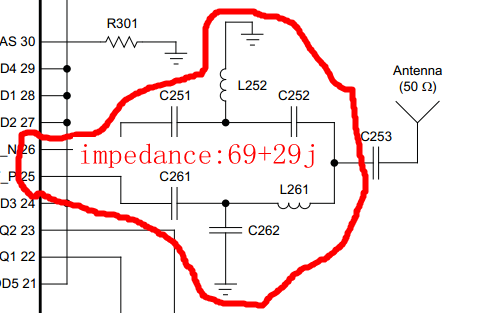
So the according to the data sheet, the optimum differential load at RF_N and RF_P is 70 +j30. However since I am using a Johansen Balun (which is said to be a conjugate match), the single-ended source impedance should then become 50ohms (or close to). Does it follow then that my pi matching circuit should match to a Smith Chart centre rather than some unspecified complex conjugate?
I have characterized my PCB and RF trace (using only a single 0R for matching). This placed the 2.45GHz impedance according a VNA at 23.9 - j12.99. Just want to verify I should match to the Smith chart centre and not the 70 + j30 point or 70 - j30 point. Thanks


