This thread has been locked.

If you have a related question, please click the "Ask a related question" button in the top right corner. The newly created question will be automatically linked to this question.

DLP-7970ABP on MSP430FR5969

Other Parts Discussed in Thread: MSP430G2553, TRF7970A, MSP-EXP430FR5969, MSP430FR5972, MSP-EXP430F5529LP, DLP-7970ABP

Hi guys, I'm approaching on this technology of nfc/rfid. I see a very good work on the TRF7970A boosterback working with a MSP430G2553 launchpad.

Now, I'd like to have the exact same behaviour with the MSP-EXP430FR5969 launchpad: is it possible? (like compatibilities, ecc.) and there is some kind of example code for me to start the development?

Thank you!

  • Hey Daniele,

    We don't have any example code running on the FR5969 Launchpad yet for the TRF7970A booster pack.  

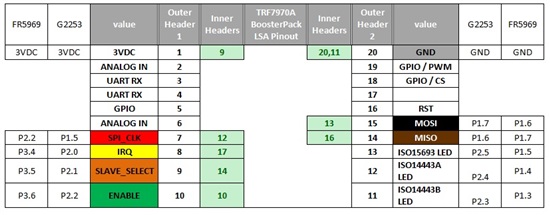
    As for the booster pack itself, it should be compatible to all current and future Launchpads.  Below is the pin out for the Boosterpack and the pins/connections on the G2553 LP and the FR5969 LP.    

    For now, you'll have to port over the code.  These are the changes that would need to be made to the code to get it ported over succesfully:

    • Clock Initialization
    • SPI Init and read/write functions
    • Interrupt Initialization 
    • ISR name 

    The NFC Code/flow shouldn't need to be touched at all.  In the future, we will provide example code on this lauchpad as well, but we are currently focusing on developing a NFC library and other new software solutions.  

    Let me know if you have any questions.  

    Thanks,

    JD

  • Thank you John, I'll give a try for the next days!

    If I'll have troubles or questions, I'll let you know!


    Bye

  • Hi John, I'm afraid I think TRF7970A is not compatible with my launchpad.

    As I see on FR5969 manual, the SPI slave select pin is programmable only on port P1.3 / P.14 and not on P3.5 as you shown me.


    In fact, after porting code, I see all modules working fine (clock, interrupts, ISRs) but the RX buffer is always empty.

    Am I wrong?

    Regards,

    DS

  • Hey DS,

    The Slave Select is not tied to the SPI module.  It's actually driven independently as a GPIO in all our code examples. 

    If you just change the Slave Select #defines in the header files to match with that Pin 3.5, it should work.  

    Try this and let me know.

    Thanks,

    JD

  • Also, a good test is to try reading a register after you write it.  If you can't read back what you wrote, then there is something wrong with your SPI communication.

    Thanks,

    JD

  • Yes, in fact I just set the port P3.5 to work as indipendent GPIO and I see that DLP is not reading anything. I'm connecting an oscilloscope to SPI pins, so I can (I wish) see what's wrong with my configuration.

    I'll let you know.

    Thanks

    DS

  • I did it!

    SPI configuration was fine, I just missed to set a clock register.

    Everything's fine... now I can proceed with other test

    Thank you,


    DS

  • Hi Daniele Spinello,

    Can you plz share the code post porting if possible..

    I am using MSP430FR5972 and yours might help me..

    Thank you in anticipation.

    Warm regards,

    Koustubh Thorat 

  • It's kind of big now my whole project, to zip it & post it... what do you need exactly? So I can give you the right files!
  • Daniele,

    I'd like to jump in here if I may.

    I am using a DLP-7970ABP Booster Pack. I ported the sample code provided by TI (for the MSP-EXP430G2X and MSP-EXP430F5529LP LaunchPads) over to my MSP-EXP430FR5969 LaunchPad. I gutted the SPI interface code and coupled the base code to my existing SPI Driver. I believe the SPI and Port pins are correctly mapped between the Booster Pack and the Eval Board. I found that I cannot communicate to the Booster Board through the SPI bus. I performed a simple register write/read and the readback value is 0x00. I read the literature on the Vin, SS, EN1, EN2 setup sequence and tried to follow it, but there is no access to EN2 and controlling the edge timing relative to the Vin signal is impossible. I looked at the SPI MOSI data to the Booster Pack and it looks perfect. The clock polarity, phase and baud looks the same as in the literature and the clock/data signals are well framed in the SPI slave select signal. I have tried adjusting the SS and EN signals to 4 mSec without any regard to the Vin signal which was TRUE a long time ago and SPI comms don't work. I tried just pulsing the EN low then high and still no luck. It looks like the Booster Pack (or the TFR7970A Tranceiver IC) is powered down and won't wake up. Any thoughts on the matter?