This thread has been locked.

If you have a related question, please click the "Ask a related question" button in the top right corner. The newly created question will be automatically linked to this question.

CC2591 failure after several days of operation

Other Parts Discussed in Thread: CC2591, CC2500

We have used thousands of CC2591 chips over about 7 years now and mostly without problems. We have recently found that some devices fail after a period of operation of possibly a few days to a few weeks while on bench test. We use the same design in various products but the fault has occurred mostly in just one. Power supply voltage is 3.3V. The operation initally seems normal. When the parts fail they no longer provide gain and we see a difference of 30 or 40dB in signal strength compared to a good device. They also draw enough current to feel a bit warm even when not transmitting or receiving. Replacing the CC2591 solves the problem. Is there a possibility of a chip production batch problem? We have not been able to identify another cause. The CC2591 is always coupled with the CC2500. The CC2500 has never failed. If the CC2591 survives more than a few weeks they seem to be OK long term and quite robust. All boards are assembled by the same production plant. Any ideas?

  • Hi Ric,


    I have asked our quality department to take a look at this case, however as most people are out on summer vacation right now, please allow some time before they come back to you.

    Can you be a bit more exact on how many failures you have found so far? Are there any chance of ESD being the issue (anything in your bench test that would cause that)? Could you provide the schematic of the RF match between the CC2591 and the antenna, and preferably also some details on what kind of antenna you are using?

    As far as I know there has not been any changes in the CC2591 production, but I will let QA confirm that.

    Regards,
    Fredrik

  • Hi Fredrik.

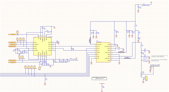
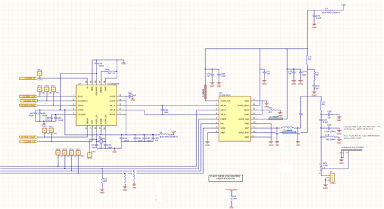
    Schematic attached. Note that the circuit mostly comes from TI application notes. The last L and C before the antenna are not placed (L14 and C85). C46 between the chips is also not placed. The PCB layout is also mostly from TI notes. The external antenna option is used rather than the PCB inverted F. We connect a 100mm coax with a UFL connector. Antennas are usually small 2dB isotropic with SMA base. We also use bigger, higher gain antennas but that is not really relevant as all bench testing is done with the isotropic. Sometimes initial testing is done with no antenna connected at all. Radio still works but signals are weak. Note also that we use the same design in about 6 different products. The product that is made in the largest quantities is where we are finding most of the problems. Batches of around 200 boards are made every month or so. We are finding that maybe up to 10 or more boards in a batch will initially test OK. The completed product is left on soak test for up to two weeks. During this period some of the CC2591s will fail. If they don't fail during this time then they seem to be OK long term no matter how they are used or what antenna is connected. The problem seems to have come up only in the last year but it is causing a lot of problems at present.

  • Hi Fredrik.


    I sent you a schematic. Any thoughts? Note that all CC2591 chips were sourced from TI Taiwan.


    Regards,


    Ric

  •  cc2591 is '****ng' device!

    maybe It is dead! ESD weak!

    careful ESD!

    Dead device current increase 100mA.

    1. Use pull down Resister at PAEN, EN and HGM.

       3 Pin All high Avoid! ( mcu reset time or mcu no control time)

       Exactly! MCU default output setting  is 'logic low'

    2. 50ohms Impedance matching  for  CC2591_11PIN


    Problems are reduced.

    However, the problem is a little generated.

    http://e2e.ti.com/support/wireless_connectivity/f/155/t/16135.aspx

  • Thank you Deok Cheol Gahng.


    This is the first good information I have received.

    If PAEN, EN and HGM are high at the same time will device fail? Will it be dead?


    Also, are you saying not to run amplifier without antenna or 50 Ohn load connected to pin 11?


    Regards,

    Ric

  • I use the Google translator.
    Will be hard to read.

    1.tx rx control
      Operation of logic high at the same time is not necessarily failing.
      However, 'pull down'  reduces the probability of failure.
      I think the 'tx to rx_ rx to tx' switching time on device dead.
      tx current = 112mA
      rx current = 3.4mA
      CC2591 is a sudden change in current seems to weaken.

      Try the following actions to try!
      default (power down) = 0.1uA (paen = en = hgm = 0)

      @ rx to tx
       -rx HGM = 3.4mA (paen = 0, en = 1, hgm = 1)
       -tx no signal (cc2500 no output) = 40mA (hgm = 0, en = 0, have some delay & paen = 1)
       -tx (cc2500 output) = 112mA

      @ tx to rx
       -tx (cc2500 output) = 112mA
       -tx no signal (cc2500 no output) = 40mA
       -rx HGM = 3.4mA (paen = 0, have some delay & en = 1, hgm = 1)


    2. Impedance matching
       cc2591 no matching behavior seems dangerous. 


    3.storage careful!
       static electricity and humidity attention.
       There are many dead cc2591 during storage.

    If it is still under development, it is another to use FEM for your mental health is the right choice.

  • Deok Cheol Gahng,

    Thank you again for your help. It is very useful. I will follow up with TI as well to find out what they know about this problem.


    Regards,


    Ric

  • Dear Ric

    There have been no major changes to the CC2591 lately that I am aware of that could be related to the reported issue.

    We have seen some cases of ESD/EOS damage related to the CC2591. Often the issue relates to SMA antenna assembly, where the customers have either had insufficient ESD protection in the assembly area and/or where the PCB design does not offer sufficient ESD protection.

    If possible, please probe the impedance of CC2591 pin 10 (AVDD) and 11 (ANT) on both a functional and a failing board and provide the results. This is a typical first step to check if there have been and ESD/EOS incident.

    Please also provide the chip top side markings on the failing devices, and I can check if they are from the same production lot(s). I will need the numbers from the YMS LLLL positions as shown in yellow below:

    CC2591

    TI YMS

    LLLL G4

    Thanks and regards,

    Bjarte Nystoyl

  • Hi Bjarte.


    I currently have two failed CC2591 chips on my desk.

    The text on the chips is as follows:

    CC2591

    TI 06J

    PCK4

    On failed chips the DC resistance measured between pins 10 and 11 is about 10 Ohms to 15 Ohms. On boards with good chips this would be MOhms.


    Regards,

    Ric Otton

  • Ric

    The DC resistance you have measured strongly suggests that the failing devices have suffered from an EOS/ESD incident. This is based on observations from other cases where EOS/ESD have been confirmed by extensive failure analysis. 

    Please ensure that all assembly is being done in an ESD protective environment. In addition I would review the design and see if you are able to increase the ESD protection, especially related to the SMA antenna. This is the most common "entry point" for ESD incidents, and this reflects one of the major advantages of using PCB antennas (though I know it is not always feasible, and SMA antennas are often easier to use when developing and testing new designs.

    Sadly, I'm not an RF Designer, so I'm afraid I can't contribute to any specifics in regard to the improvement of the design and layout. Hopefully you will benefit from the previously posted advices and possibly further input from our application engineers.

    Best regards,

    Bjarte

  • Hi Bjarte.


    Have you been able to confirm whether the batch of CC2591 chips we are using is particularly susceptible to failure? The problem we have observed has affected about 5% to 10% of boards produced in recent months. We have not noticed it prior to this or at least the problem has been so infrequent that the boards may have been rejected and the problem not diagnosed. Also, if boards pass our two week production testing cycle, without failing, they seem to be reliable long term. This suggests that perhaps not all chips are of the same quality but that the good ones are robust.


    Regards,


    Ric

  • Hi Ric.

    There have not been other reported issues with other units from the same production lot.

    I would like to ask some questions regarding your production process. The answers might contain details you would not want disclosed to the public. I will send them to your e-mail address shortly, so that we can continue the conversation there.

    Regards,

    Bjarte