This thread has been locked.

If you have a related question, please click the "Ask a related question" button in the top right corner. The newly created question will be automatically linked to this question.

CC120XEM-868-930-RD: transparent serial mode ASk/OOK

Part Number: CC120XEM-868-930-RD

Hi,

I am trying to use the CC1200 in transparent serial mode with an ASK/OOK RF signal.

I try to get the decoded signal to IOCFG0.

For test puropse I did the following:

Reset the device

Select the generic config  symbol rate 4.8kps, OOK, RX BW 128Khz

Changed the frequency to 916.5

SYNC_CFG1:SYNC_MODE = 0

IOCFG0 = 9

PREAMBLE_CFG1:NUM_PREAMBLE =0

MDMCFG1:FIFO_EN = 0

PKT_CFG2:PKT_FORMAT = 3

MDMCFG0:TRANSPARENT_MODE_EN=1

I send an SCAL command to calibrate the device

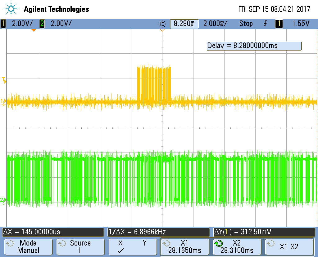
I send an SRX cmd to go in RX mode and I get the following data on IOCFG0 (see attached picture).

in yellow, I have the signal decoded by a CC1101 device configured in tranparent serial mode (note that the signal symbol rate is 100kps).

In green the signal out of the demo kit. I was expecting to have a flat output put I can see 

I go to IDLE

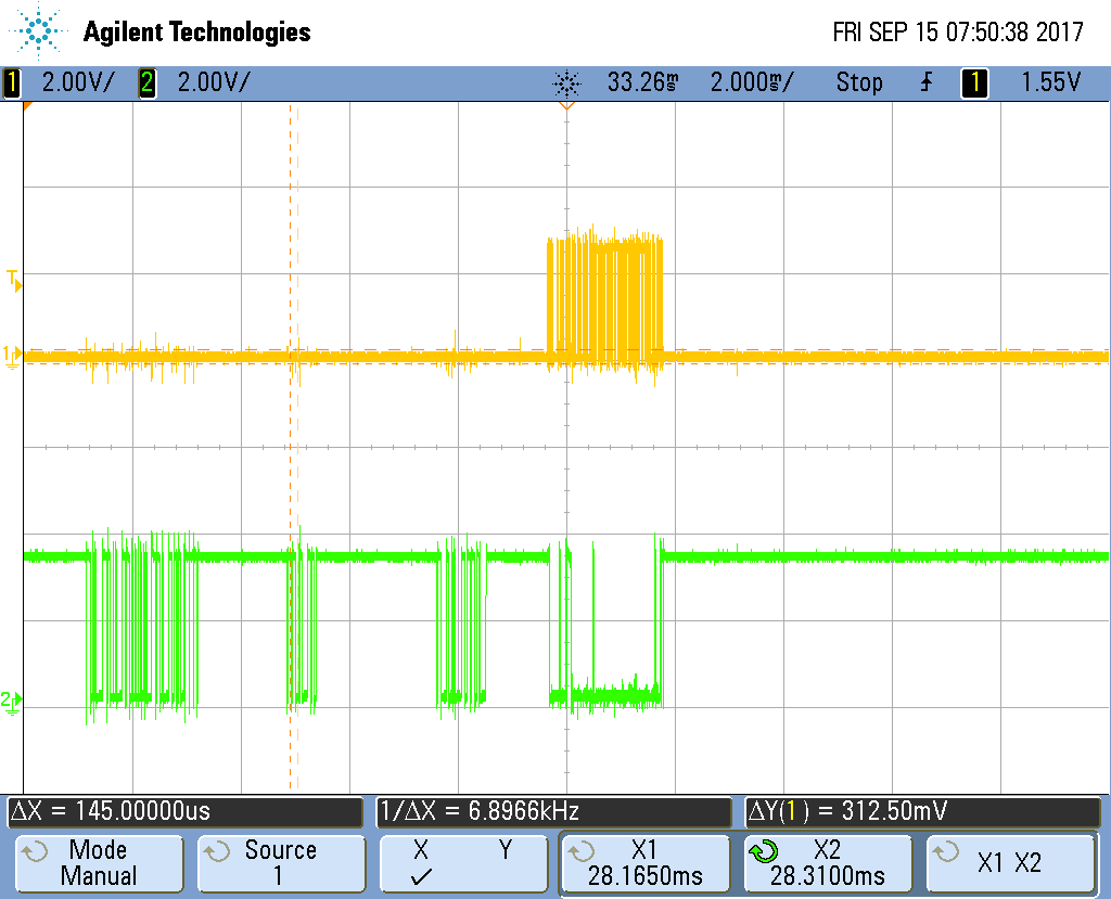
Changed MDMCFG2.IPSAMPLER_P to 2

Changed the RX Filter BW to 400 (416.666)

Changed the symbol rate to 100kps and go back to RX I get the following

Why is there all the "noise" on the output of the demo kit,

Is there any specific configuration I should change to avoid toggling of the serial output.

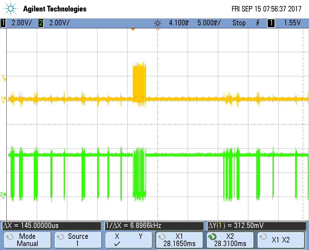
I made a last change, I removed the antenna and got this.

  • When the CC1200 is in transparent mode and there is no signal on the air it will demodulate noise and this is what you get on the GPIO.
    Any particular reason for not using synchronous serial mode or FIFO mode?
  • We use a specific custom signal and cannot be decoded by the chip. We used in the previous version of our product line the CC1101 to output the demodulated signal on the IOCFG line (yellow signal on the picture) so there should be a way to configure the CC1200 to get the same result?
    Here is the config of the CC1100 chip
    RF_SETTINGS const rfSettings = {
    0x0A, // FSCTRL1 Frequency synthesizer control.
    0x00, // FSCTRL0 Frequency synthesizer control.
    0x21, // FREQ2 Frequency control word, high byte. 868.3 MHz is default
    0x65, // FREQ1 Frequency control word, middle byte.
    0x6A, // FREQ0 Frequency control word, low byte.
    0x4D, // MDMCFG4 Modem configuration. RX_BW = 406 kHZ - in version 0.9
    0x3B, // MDMCFG3 Modem configuration.
    0x30, // MDMCFG2 Modem configuration. asynchronus transparent mode
    0x22, // MDMCFG1 Modem configuration.
    0xF8, // MDMCFG0 Modem configuration.
    0x00, // CHANNR Channel number.
    0x00, // DEVIATN Modem deviation setting (when FSK modulation is enabled).
    0xB6, // FREND1 Front end RX configuration.
    0x11, // FREND0 Front end TX configuration.
    0x18, // MCSM0 Main Radio Control State Machine configuration.
    0x1D, // FOCCFG Frequency Offset Compensation Configuration.
    0x1C, // BSCFG Bit synchronization Configuration.
    0xC7, // AGCCTRL2 AGC control.
    // 0xFF, // AGCCTRL2 AGC control.
    0x00, // AGCCTRL1 AGC control.
    0xB2, // AGCCTRL0 AGC control.
    0xEA, // FSCAL3 Frequency synthesizer calibration.
    0x2A, // FSCAL2 Frequency synthesizer calibration.
    0x00, // FSCAL1 Frequency synthesizer calibration.
    0x1F, // FSCAL0 Frequency synthesizer calibration.
    0x59, // FSTEST Frequency synthesizer calibration.
    0x88, // TEST2 Various test settings.
    0x31, // TEST1 Various test settings.
    0x09, // TEST0 Various test settings.
    0x0D, // IOCFG2 GDO2 output pin configuration. serial transparent data output
    0x0D, // IOCFG0D GDO0 output pin configuration. use for tx in transparent mode
    0x04, // PKTCTRL1 Packet automation control.
    0x32, // PKTCTRL0 Packet automation control. ask / ook
    0x00, // ADDR Device address.
    0xFF // PKTLEN Packet length.
    };
  • on the CC1101 chip to avoid all the noise we do reduce the maximum allowable DVGA gain. AGCCTRL2.MAX_DVGA_GAIN, which register configruation can be used to do the same on the CC1200? I already set the MDMCFG1.DVGA_Gain to 1
  • When you demodulate noise (i.e. when there is no signal present on the antenna) you will get noise on the data output in asynchronous serial mode. What you can do is to enable carrier sense (CS)  flag on one of the GPIO. Use this as an interrupt to the interfacing MCU and only start to look for valid data when CS is asserted.