In last month’s post, I talked about the relationship between an external reference on the output stage of the DRV411 and the common-mode output of the H-bridge compensation-coil drive stage. This month, I’ll take a look at motor drives and industrial controllers where the current sensor needs to be powered from a bipolar supply rail. Closed-loop current sensors provide a highly accurate representation of either AC or DC current and sometimes need a wider-output voltage range than what the DRV411 can provide when used with a single 5 V supply. The TIPD184 reference design for a dual-supply closed-loop current sensor system, in the TI Designs Precision library, shows how to use the DRV411 in an application where the output voltage from the current sensor provides a bipolar swing.
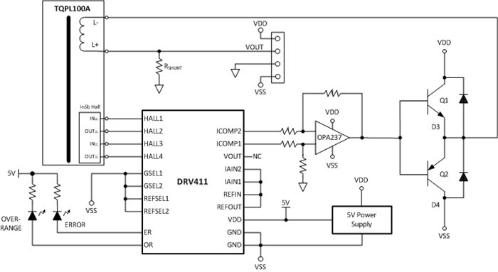
In the TIPD184 isolated current sensor design, the power rails are designed to be operated from ±6V to ±18V. The output of the sensor is designed to be 0 V when no current is flowing through the primary conductor. To accomplish this, the DRV411 ground terminal is connected to the negative rail (VSS) and powered from a 5 V low-dropout (LDO) regulator, which is also referenced to VSS. The TPS79850 LDO is connected to the positive supply rail (VDD) and has an input voltage range of 40 V, giving 4 V of headroom to the supply rails.
Figure 1: DRV411 and TPS79850 referenced to VSS
Figure 1 provides details on the connections used to realize a bipolar output from the sensor. In this circuit, the OPA237 is connected as a difference amplifier in a manner similar to the amplifier found inside the DRV411. In this case, the reference node of the difference amplifier is tied to analog ground and the power rails are tied to VDD and VSS. With no current flowing through the primary, the output voltage from the sensor is 0 V.
The TQPL100A shown in Figure 1 is a passive sensor module from Topstek that contains a 2,000-turn compensation coil and a symmetrical hall sensor. The TI Designs Precision reference design was set up as a ±100A sensor with an output voltage of ±2.5 V. The shunt resistor was selected based on the desired output voltage, while the turns ratio of the sensor can be expressed as Equation 1:
At the end of the day, changing the bipolar swing of the output-voltage range is as simple as changing the shunt resistor.
Additional resources:
- Application note: Design Considerations for the DRV411.
- Blog post: Make sense of an uncommon reference.
- Read more about the TIPD184, a dual-supply closed-loop current sensor solution designed to accurately measure DC, AC and pulsed currents to +/-100A with galvanic isolation between the primary and secondary circuits.
- Get the most-used analog-to-digital conversion formulas in one handy guide.


