

My birthday is this month; every year I remind my friends how much engineers HATE surprises. Whether it’s a surprise in our social lives or a surprise in a project, anything unexpected is unwelcome. In analog circuits, a very unwelcome surprise is the noise produced by active filter circuits. After all, active filters are supposed to remove noise!
All active circuits produce some amount of noise and filters are no different. We can uncover the source of this noise by looking at their noise gain. Noise gain is a term used to describe the amount of amplification that a circuit applies to its intrinsic noise source(s). In a typical op amp circuit, the noise gain is measured from the non-inverting input.
Figure 1 shows the TINA-TITM simulation circuit I used to measure the noise gain of two 2nd-order, Butterworth, 1kHz low pass filters. One circuit uses the Sallen-Key (SK) topology and the other uses a multiple feedback (MFB) topology. To measure the noise gain of an active filter, the signal input is grounded and a signal source is inserted in series with the op amp non-inverting input.
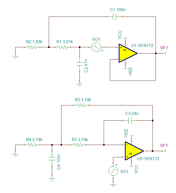
Figure 1: Circuit configuration for measuring the noise gain of Sallen-Key (top) and multiple feedback (bottom) active filters.
Performing an AC transfer characteristic analysis on the two circuits reveals their noise gain:

Figure 2: The noise gain of 1kHz, Butterworth lowpass filters. An MFB filter is shown in Blue and the SK filter is shown in red.
Although these two circuits have identical filter characteristics (signal gain and attenuation, Q, corner frequency), their noise gain is quite different! Notice that the MFB filter has a noise gain of 6dB in the pass band because the op amp is in an inverting configuration.
Also notice the increase in the noise gain which occurs near the filter’s corner frequency. The magnitude of this noise gain “hump” is proportional to the quality factor, or Q, of the filter. To illustrate that point, we can compare several SK filters with the same signal gain and corner frequency, but different Q values.
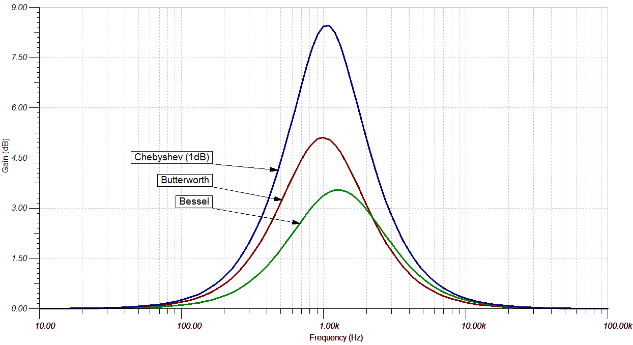
Figure 3: Noise gain comparison of SK low pass filters of differing Q values
Higher Q filters have substantially greater noise gain near their corner frequency and this affects the total integrated noise. I used TINA-TI to simulate the total integrated noise of 3 SK low pass filters in a 10kHz bandwidth, all built with the OPA172. The corner frequency of the filters was identical (1kHz) but their Q values were different. The results are summarized in Table 1.
Table 1: Total integrated noise in a 10kHz bandwidth of SK filters with different Q values.

Engineers often select higher Q filters for their greater attenuation, without considering the increase in noise from the filter itself!
Here is a list of my basic rules for low noise filter design. I tried to implement all these design practices in my most recent TI Precision Design: An Analog, Active Crossover Network for Two-Way Loudspeakers.
Basic Rules for Low Noise Filter Design
- Use the Sallen-Key topology if possible.
- Avoid high Q filters if a low Q filter can do the job.
- Use the lowest resistor values possible as long as you:
1. Use high quality capacitor types (film or NP0/C0G ceramics). Other types of capacitors may produce distortion, as I show here and here.
2. Avoid excessively loading the op amp or other circuits.
- Pay attention to the source impedance presented to the op amp. A FET input op amp may provide lower noise when the filter resistor values are large.
- Place low pass filters at the end of the signal path to attenuate the noise of preceding circuits.
Following these rules can help avoid some of the unwanted surprises we engineers have to cope with on a daily basis!

