This thread has been locked.

If you have a related question, please click the "Ask a related question" button in the top right corner. The newly created question will be automatically linked to this question.

[FAQ] How to synchronize the PRU IEP timer with Linux system time?

I am using a Sitara processor with a Linux core, a time sync router, and a PRU subsystem (AM62x, AM64x, AM65x). I want to synchronize the Linux system time with an IEP timer in the PRU subsystem. How do I do it?

We will use AM64x for this example, but the same concepts will apply to all of the processors.

.

AM64x Time Sync Router: reference [FAQ] AM64x: What is the Time Sync Router for? How do I use it?

AM62x Time Sync Router: reference [FAQ] AM62: What is the Time Sync Router for? How do I use it?

For more information about other Sitara multicore subjects, reference [FAQ] Sitara multicore development and documentation. More information about PRU specifically can be found in the PRU Development subsection.

  • Overall design

    Let's assume you are synchronizing the Linux system time to an external clock source over Ethernet PTP.

    Then you want to use a PPS signal from the CPTS (inside the CPSW) to synchronize the Linux system time with the IEP counter.

    After doing an initial read of the Linux system time, then the PRU can wait on the rising or falling edge of the PPS signal to re-sync itself to the Linux system time every second.

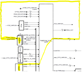
    Look at the AM64x Technical Reference Manual (TRM), figure "SoC Time Sync Architecture". This is the path the PPS signal will take from the CPTS, to the PRU subsystem:

  • Step 1: taking a PPS signal from the CPTS and routing it somewhere

    Starting in SDK 9.0, there is updated documentation on how to get a PPS signal to go from the CPTS and loop back to itself to generate a CPTS timestamp in the SDK docs: https://software-dl.ti.com/processor-sdk-linux/esd/AM64X/09_00_00_03/exports/docs/linux/Foundational_Components/Kernel/Kernel_Drivers/Network/CPSW-PTP.html

     * section "Time stamping external events" discusses how to set up the loopback

     * section "PPS Pulse Per Second support" discusses how to set up PPS

    Let's check the AM64x SK evm file from SDK 9.0, k3-am642-sk.dts:

    #define TS_OFFSET(pa, val)     (0x4+(pa)*4) (0x10000 | val)
    
    &timesync_router {
            status = "okay";
            pinctrl-names = "default";
            pinctrl-0 = <&cpsw_cpts_pps>;
    
            /*
             * Use Time Sync Router to map GENF1 input to HW8_TS_PUSH output as well
             * as the PRU ICSSG0 SYNC1 output.
             */
            cpsw_cpts_pps: cpsw-cpts-pps {
                    pinctrl-single,pins = <
                            /* pps [cpts genf1] in22 -> out37 [cpts hw8_push] */
                            TS_OFFSET(37, 22)
                            /* pps [cpts genf1] in22 -> out26 [SYNC1_OUT pin] */
                            /* Note: NOT actually SYNC1_OUT. See Step 2 for details */
                            TS_OFFSET(26, 22)
                            >;
            };
    };

    One input signal to the time sync router can be routed to multiple outputs. The CPTS PPS signal is also getting routed to an external SYNC_OUT pin, where it can be observed with an oscilloscope.

  • Step 2: configure the time sync router to send the PPS signal to the PRU 

    Add an entry to the time sync router in the Linux devicetree that goes to one of the PRU signals.

    The inputs and outputs of the time sync router are different for every processor.

    Inputs and Outputs of the time sync router are listed in the TISCI documentation, the associated e2e FAQ, or the Technical Reference Manual (TRM). Different sources have slightly different information in them:

    TISCI docs, AM64x Time Sync Router Inputs

    TISCI docs, AM64x Time Sync Router Outputs

    [FAQ] AM64x: What is the Time Sync Router for? How do I use it?

    Let's take another look at the AM64x SK evm file from SDK 9.0, k3-am642-sk.dts. We will check which inputs and outputs are currently configured:

    1 input signal, from input 22
    The TISCI docs say that this is the cpts_genf1 signal, coming from the CPSW subsystem's CPTS (not the main domain CPTS)

    2 output signals:
    output 37: The TISCI docs say that cpts_hw8_push goes back to be timestamped by the CPSW CPTS
    output 26: The TISCI docs don't say what this is, so we have to refer to the e2e FAQ or the TRM. It is actually the SYNC2_OUT pin (NOT the SYNC1_OUT pin as commented in the SDK 9.0 devicetree file). SYNC2_OUT is not routed to a header pin on AM64x EVM. In order to see the PPS signal on a header pin, try routing to SYNC0_OUT instead, and changing the pinmuxing for D18 from ECAP to SYNC0_OUT.

    So we have to configure another output if we want a signal to go to a PRU subsystem.

    Use one of the pr1_edc[0:1]_latch[0:1]_in outputs to route the signal to one of the PRU subsystem instances.

  • Step 3: Configure PRU to receive the PPS signal 

    Let's take a closer look at the AM64x time sync router outputs that go to a PRU subsystem:
    TISCI docs, AM64x Time Sync Router Inputs

    Destination Name Destination Interface
    AM64X_DEV_PRU_ICSSG0 pr1_edc0_latch0_in
    AM64X_DEV_PRU_ICSSG0 pr1_edc0_latch1_in
    AM64X_DEV_PRU_ICSSG0 pr1_edc1_latch0_in
    AM64X_DEV_PRU_ICSSG0 pr1_edc1_latch1_in
    AM64X_DEV_PRU_ICSSG1 pr1_edc0_latch0_in
    AM64X_DEV_PRU_ICSSG1 pr1_edc0_latch1_in
    AM64X_DEV_PRU_ICSSG1 pr1_edc1_latch0_in
    AM64X_DEV_PRU_ICSSG1 pr1_edc1_latch1_in

    Each ICSSG instance has 4 inputs that come from the time sync router. Each ICSSG instance has 2 IEP timers, and each IEP timer has two EDC latch inputs. Thus, pr1_edc0_latch[0:1]_in goes to IEP0, and pr1_edc1_latch[0:1]_in goes to IEP1.

    Those 4 signals are mapped to these Capture input registers, as per TRM table "IEP Timer Mode Mapping"

    To configure the IEP timer to capture these latch inputs, follow the steps in TRM section "PRU_ICSSG IEP Timer Basic Programming Sequence" > "Capture function".

    Now we have the PRU inputs. When a rising or falling edge is detected, the IEP capture register will contain the IEP timestamp from the exact time that edge was detected. Then the global capture event will be triggered in the PRU INTC. But which event will be the one to get triggered?

    Reference TRM section "PRU_ICSSG Interrupt Requests Mapping"

    Event #56 pr0_iep1_any_cmp_cap_pend the global capture event from IEP1
    Event #7 pr0_iep_tim_cap_cmp_pend the global capture event from IEP0

    Since the PPS signal is expected to come once a second, the PRU core can measure the difference between the IEP capture timestamp and the expected IEP time, and then adjust the IEP counter accordingly.