This thread has been locked.

If you have a related question, please click the "Ask a related question" button in the top right corner. The newly created question will be automatically linked to this question.

[FAQ] AM64x: What is the Time Sync Router for? How do I use it?

Part Number: AM6421

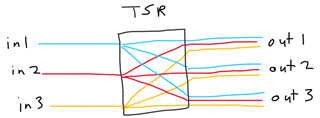
AM64x has interrupt routers, just like any other processor. But it also has an interrupt router called the Time Sync Router (TSR) that is designed to route an input interrupt to multiple output interrupts. What is the TSR for? The documentation is not very clear at the moment, so how do I use it?

.

For information about Time Sync Router on AM62x, reference this FAQ: e2e.ti.com/.../faq-am62-what-is-the-time-sync-router-for-how-do-i-use-it

  • The Time Sync Router (TSR): An Overview

    The TSR is designed to send one sync signal to multiple recipients. This sync signal allows multiple peripherals or cores within the processor to synchronize their counters to a single "master clock". TSR signals can even be routed to processor pins if the sync signal also needs to be received by a device external to the processor.

    There are 2 latencies that matter here:
    1) The latency for a signal to travel from signal source (e.g., in1) to the input of the TSR. We call this input latency
    2) The latency for a signal to travel from the input of the TSR, to the output of the TSR, to the input of your destination (e.g., out1, out2). We call this router + output latency

    The input latency for AM64x will be less than 10ns.

    When we tested router + output latency, we split it into two cases:
    Case 1: Test all TSR outputs that are inside the AM64x processor (e.g., PRU and a CPTS are inside the AM64x processor)
    Case 2: Test all possible TSR outputs, including the SYNC_OUT processor pins

    For Case 1, the router + output latency is more than 0ns, and less than 4ns. Thus, the difference in time for a single input to reach two different outputs inside the processor will always be less than 4ns.
    For Case 2, the router + output latency is more than 0ns, and less than 14ns. Thus, the difference in time for a single input to reach two different outputs when one of the outputs is a processor pin will always be less than 14ns.

    So what does that actually mean? Let's say we send a GTC push event to CPTS, to PRU, and to the SYNC_OUT pin. It will take between 0 and 13ns for the GTC push event to reach the CPTS, between 0 and 13ns for the GTC push event to reach the PRU, and between 0 and 23ns for the GTC push event to show up on the SYNC_OUT pin. Since this a single input signal, that means the input latency is the same for all of these destinations. So if we are just looking at the difference in arrival times, we can ignore input latency. The push event will arrive at the CPTS and the PRU cores within 4ns of each other. The push event will arrive at the SYNC_OUT pin within 14ns of arriving at the CPTS and PRU cores.

    There will be additional latencies. For example, once the signal reaches the SYNC_OUT pin, the signal will take additional time to travel along board traces, and into whatever external device you wish to sync. If the sync signal is routed to an A53, R5F, or M4F core, then the signal must first pass through the Interrupt Aggregator as described in the "TSR Hardware Documentation" section below. If the sync signal is interrupting a core running a higher level operating system, it will take additional time for that core to switch contexts and address the interrupt. A note on sending sync signals to processor cores: If high precision / low latency is needed, I generally suggest using RTOS or NORTOS (i.e., bare metal) cores instead of Linux cores.

    TSR Software: still under construction

    Added May 24, 2023:

    The SYSFW code has now been updated so that a single input can be routed to multiple outputs in both the time sync router and (as of SDK 8.6) the compare event router (fixing the issue reported in this thread). For more information about configuring the time sync router or the compare event router from the Linux devicetree, reference thread Interrupt routers with Linux boot flow.

    TSR Hardware Documentation: still under construction

    At this point, we are still cleaning up the time sync router documentation in the Technical Reference Manual (TRM).

    TSR Registers

    From the TRM memory map, we know
    TIMESYNC_EVENT_INTROUTER0_CFG starts at 0x000A40000

    The register definitions are not currently included in the TRM. However, when I checked the design files, the TSR registers are formatted like the MAIN_GPIOMUX_INTROUTER0_CFG registers. So the TSR registers look like this:

    Offset  Acronym  Register Name TIMESYNC_EVENT_INTROUTER0_CFG
    Physical Address
    0h TIMESYNC_EVENT_INTROUTER0_PID  Peripheral identification register  00A4 0000h
    4h + formula TIMESYNC_EVENT_INTROUTER0_INTR_MUXCNTL_n  Interrupt mux control register  00A4 0004h + formula

    And the MUXCNTL register definition looks like this:

    Interrupt mux control register. Offset = 4h + (n * 4h); where n = 0h to 28h. (i.e., there are 41 TSR outputs total)

    GPIOMUX_INTRTR0_MUXCNTL_n Register Field Descriptions
    Bit  Field  Type  Reset  Description
    31-17  RESERVED  R  0h  Reserved
    16  INT_ENABLE  R/W  0h  Enable for interrupt output N. 0h = Disabled. 1h = Enabled
    15-6  RESERVED  R  0h  Reserved
    5-0  ENABLE  R/W  0h  Mux control for interrupt output N. Program this field according to
    TIMESYNC_INTRTR0 Interrupt Map.
    Note: Avoid programming this register when input interrupts are
    active. This could lead to spurious asynchronous output toggles
    which may lead to unpredictable behavior.

    TSR INPUTS

    As of AM64x TRM Revision C, the Time Sync > Time Sync and Compare Events is still blank. You can find the list of inputs to the TSR in section
    Interrupts > Time Sync and Compare Interrupt Events > TIMESYNC_INTRTR0 Interrupt Map.

    TSR OUTPUTS

    As of AM64x TRM Revision C, this is not well documented. If you go the different output sources, you will often find the TSR outputs documented in the signal lists or the diagrams. However, there is not a single list of all outputs at this point in time. Here is a rough list I generated from the design files:

    timesync_event_introuter_out_0 l2g_event_pend.8
    timesync_event_introuter_out_1 l2g_event_pend.9
    timesync_event_introuter_out_2 l2g_event_pend.10
    timesync_event_introuter_out_3 l2g_event_pend.11
    timesync_event_introuter_out_4 l2g_event_pend.12
    timesync_event_introuter_out_5 l2g_event_pend.13
    timesync_event_introuter_out_6 l2g_event_pend.14
    timesync_event_introuter_out_7 l2g_event_pend.15
    timesync_event_introuter_out_8 icssg_0.pr1_edc0_latch0_in
    timesync_event_introuter_out_9 icssg_0.pr1_edc0_latch1_in
    timesync_event_introuter_out_10 icssg_0.pr1_edc1_latch0_in
    timesync_event_introuter_out_11 icssg_0.pr1_edc1_latch1_in
    timesync_event_introuter_out_12 icssg_1.pr1_edc0_latch0_in
    timesync_event_introuter_out_13 icssg_1.pr1_edc0_latch1_in
    timesync_event_introuter_out_14 icssg_1.pr1_edc1_latch0_in
    timesync_event_introuter_out_15 icssg_1.pr1_edc1_latch1_in
    timesync_event_introuter_out_16 main_cpts.cpts_hw1_push
    timesync_event_introuter_out_17 main_cpts.cpts_hw2_push
    timesync_event_introuter_out_18 main_cpts.cpts_hw3_push
    timesync_event_introuter_out_19 main_cpts.cpts_hw4_push
    timesync_event_introuter_out_20 main_cpts.cpts_hw5_push
    timesync_event_introuter_out_21 main_cpts.cpts_hw6_push
    timesync_event_introuter_out_22 main_cpts.cpts_hw7_push
    timesync_event_introuter_out_23 main_cpts.cpts_hw8_push
    timesync_event_introuter_out_24 SYNC0_OUT pin
    timesync_event_introuter_out_25 SYNC1_OUT pin
    timesync_event_introuter_out_26 SYNC2_OUT pin
    timesync_event_introuter_out_27 SYNC3_OUT pin
    timesync_event_introuter_out_28
    timesync_event_introuter_out_29 pcie.pcie_cpts_hw2_push
    timesync_event_introuter_out_30 cpsw.cpts_hw1_push
    timesync_event_introuter_out_31 cpsw.cpts_hw2_push
    timesync_event_introuter_out_32 cpsw.cpts_hw3_push
    timesync_event_introuter_out_33 cpsw.cpts_hw4_push
    timesync_event_introuter_out_34 cpsw.cpts_hw5_push
    timesync_event_introuter_out_35 cpsw.cpts_hw6_push
    timesync_event_introuter_out_36 cpsw.cpts_hw7_push
    timesync_event_introuter_out_37 cpsw.cpts_hw8_push
    timesync_event_introuter_out_38 epwm0_sync.input2
    timesync_event_introuter_out_39 epwm3_sync.input2
    timesync_event_introuter_out_40 epwm6_sync.input2

    Most of these events go straight to the target, like ICSSG, the CPTS in the main domain or in the CPSW, the PCIE, the EPWMs, or the processor SYNCn_OUT pins. However, any TSR events that go to the A53 (through the GIC), an R5F core, or the M4 cores first go through something called the L2G, then the Event Transport Lane (ETL), then they finally arrive at the Interrupt Aggregator (IA). The Interrupt Aggregator can then interrupt any of those cores.

    At this point in time, I have not done much research into TSR sending interrupts to the GIC/R5F/M4 through the Interrupt Aggregator. The latency measurements I provided above measured from the input of the TSR, to the input of the L2G logic. So it will take an unknown additional amount of nanoseconds for the signal to get through the Interrupt Aggregator and reach those cores. Anyone who is curious about doing a deep dive on these TSR outputs can start in the TRM with "DMSS L2G Interrupt Inputs", "DMSS Interrupt Requests", and the section "Data Movement Subsystem (DMSS)".

    Regards,

    Nick

  • QUESTION: The TSR allows for a single input interrupt signal to be routed to multiple outputs. But can I use the TSR to route multiple input interrupts to a single output?

    ANSWER: No.

    The Time Sync Router was designed to enable one-to-many mappings. However, each output can only have a single input. This is limited by the register control scheme. Each output has a register. The number of the input that is mapped to that output is programmed as a hexadecimal value. Since there is only one hexadecimal field, there can only be one input per output. For more details, see “TSR Registers” section above.