


Part Number: LMH6629
Hi
According to 10.2 Layout Example in the datasheet, the evaluation board is 4 layers stack up.
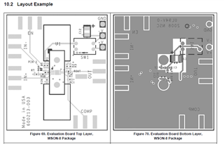
I would like to clearly identify the tracing and every layer before a board fabrication
Could you please help to confirm whether the following layer definition is correct or not?
L1 (top layer) : Signal route
L2 (mid layer 1) : GND Plane
L3 (mid layer2) : V+ Plane
L4 (bottom layer) : V- Plane
Any recommendation for layout technique not mentioned in the datasheet is also welcome
Thanks
Regards
Ben
