This thread has been locked.

If you have a related question, please click the "Ask a related question" button in the top right corner. The newly created question will be automatically linked to this question.

OPA569: OPA569 parallel connection

Part Number: OPA569

Hi,

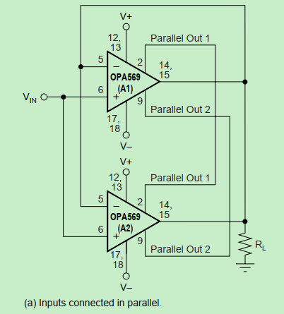
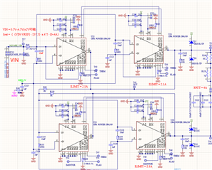
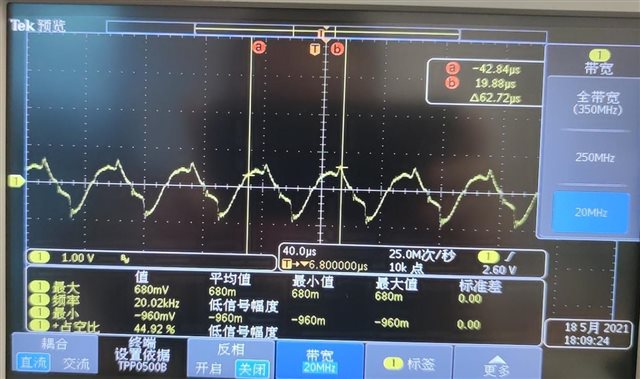
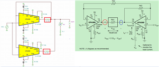
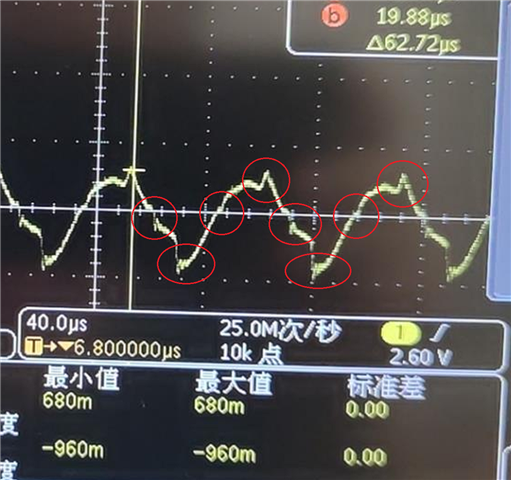
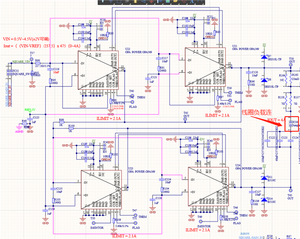
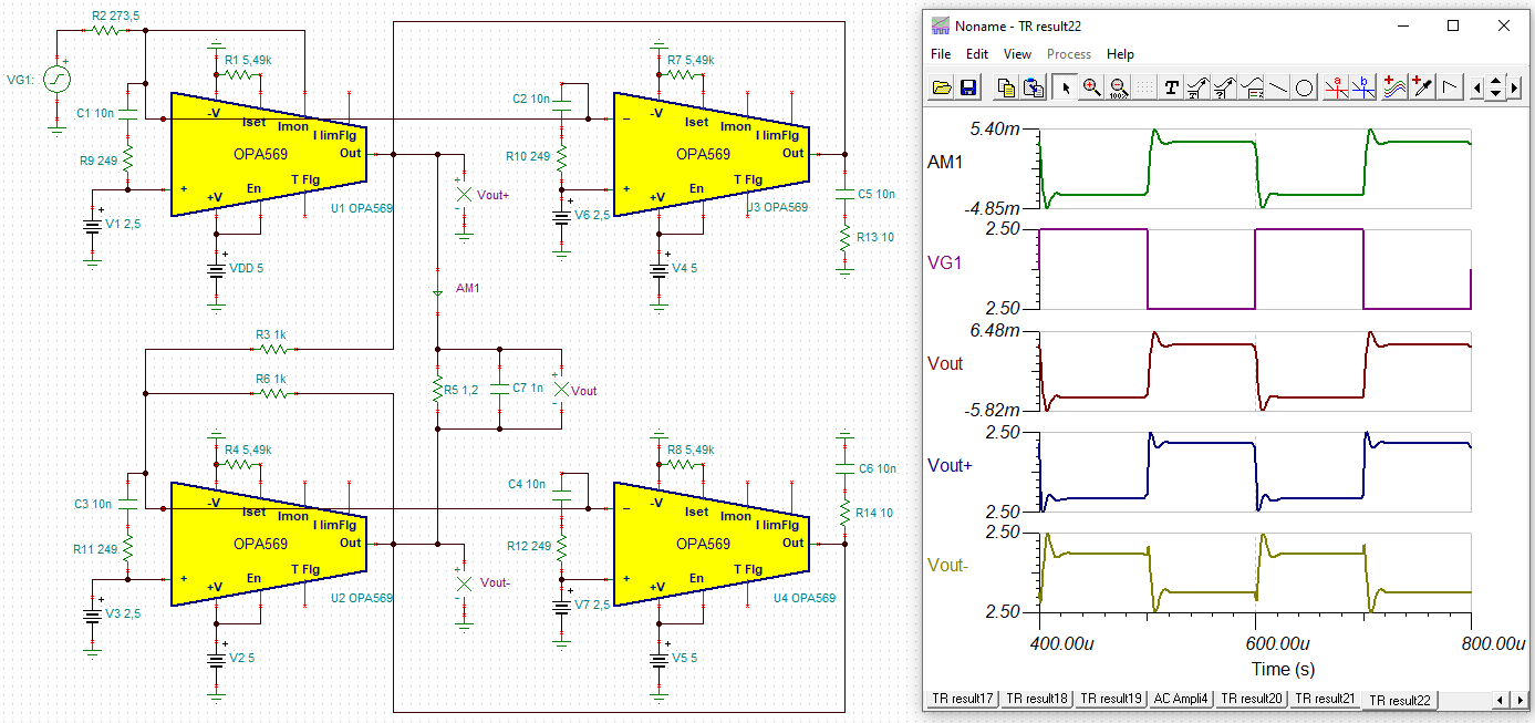
One customer used multi OPA569 in parallel with signal frequency is 20KHz to improve output current, but he found that the output waveform is fluctuate as below. But if he decrease the frequency, the output waveform is improved obviously. 


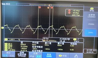
The capacitive load  has been replaced by the resistor, so it isn't the capacitor caused the fluctuate.

Best regards

Kailyn 

  • Hi Kailyn,

    the schematic cannot be deciphered. Can you please post again?

    Kai

  • Hi Kailyn,

    As Kai commented the schematic cannot be deciphered, and I would like to add neither is the O-scope image. The images are too small to see any details. Are these results obtained from the first look the customer had of their circuit design's performance?

    It is not clear from what I can see of the O-scope image is if the expected output waveform is supposed to be a clean sine wave, or if the distorted waveform is just occurring on its own? You mention decreasing the frequency from 20 kHz to something lower improves the waveform. Therefore, I suspect that the problem is sine wave distortion at 20 kHz?

    Regards, Thomas

    Precision Amplifiers Applications Engineering

  • Hi,

    Thank you very much for your reply. Yes, if decrease the frequency lower than 20KHz, the waveform is improved. But the  inputs are connected in parallel, this parallel operation couldn't degrade  bandwidth.  I attached the schematic and image again. and he referred below two circuits.

    Best regards

    Kailyn 

  • Hello Kailyn,

    Thank you for the additional information.

    Twenty kilohertz is within the useable frequency range of the OPA569, but it is getting into the frequency region where the open-loop gain (Aol) and power supply rejection ratio (PSRR) are only about 40 dB. When  they are that low relative to what they are at low frequencies the op amp performances degrade. Certainly, because the Aol and PSRR improve as the frequency is lowered that is likely the reason the performance appears to improve. Additionally, I am not sure the combined PSRR for 4 devices having paralleled outputs maintains as well across frequency as compared to a single op amp. The voltage offsets of each of the op amps being used is different from one another and can affect how each op amp performs in a parallel output circuit.

    I would like to know more about the application's power supply, and the power supply decoupling. Sometimes, when glitching or spiking is observed on an output waveform it is due to power supply switching noise coupling through to the op amp output. Often, this gets worse as frequency is increased due to the op amp's lower PSRR. The OPA569 datasheet shows in FIGURE 1, Basic Connections, the recommended power supply decoupling. The smaller schematic you provided appears to show several power supply bypass capacitors connected to the V+ pin of each OPA569 and they may be okay.

    Is the load indeed a TEC? If a clearer, larger image of that complete schematic could be provided that would prove more useful than the simplified schematic.

    Regards, Thomas

    Precision Amplifiers Applications Engineering

  • Hi Kailyn,

    Per your description, the parallel circuit is driving TEC as load, where TEC is floating. This is a typically done in DC voltage on both side. I do not understand why you are talking about "But if he decrease the frequency, the output waveform is improved obviously". 

    As Thom pointed out, please make sure that power supply is able to drive TEC directly without load issues (voltage and current) for a given TEC cooling and heating range. With OPA569 Op Amps + TEC, the power supply will take even more load due to the efficiency of the device and power dissipation at op amps. 

    If your input is DC and you observed AC at the TEC load, then the op amps are oscillating at output. The oscillatory effects are likely due to the capacitance of TEC load. Do you have a PSpice model of the TEC or datasheet of the TEC? If you do not have either, please measure it with LCR meter. We'd like to know R and C of the Peltier cooler. 

    Can you email the original schematic to our internal email? The image is still unreadable. 

    Best,

    Raymond  

  • Hi Kailyn,

    We still do not have all the load information about your parallel OPA569s driving TEC. It will be good to provide us with TEC's load characteristics and operating voltage and current. 

    A couple additional suggestions are:

    1. Place a resistor at the output of each OPA569 - We need to know TEC's driving current and voltage to recommend the resistor. 

    2. Please measure the output of TEC with respect to ground at marked red and blue circles. 

    3. We may have to limit the BW of parallel OPA569s depending on TEC data and probing information observed in step 2. 

    4. We'd like to know if power regulators are able to drive OPA560s and TEC all together without load regulator issues. The application's power supply has to drive 4 of OPA569s + TEC loads (requested from last Friday's replies).   TEC has a very low efficiency in heating/cooling, which it may draw a significant amount of current, especially when its thermal interface is not coupled properly with heat sinks/fans. 

    https://e2e.ti.com/blogs_/archives/b/thesignal/posts/paralleling-op-amps-is-it-possible

    If you have additional questions, please let us know. 

    Best,

    Raymond

  • Whew, what an exotic circuit. All this paralleling, all the snubbers between the inputs of OPA569 and on top of all that the bridging. No, that's too much. That's no elegant circuit. Dimensioning the four snubbers alone sounds like a nightmare Scream

    I would highly recommend to redesign this circuit.

    Kai

  • Hi Kai

    This customer is also ask me same question ,could I have your email ,so we can talk in email together.

    BR

    Gabriel Wang

  • Hi Gabriel and Kailyn,

    In my previous response I asked "I would like to know more about the application's power supply, and the power supply decoupling. Sometimes, when glitching or spiking is observed on an output waveform it is due to power supply switching noise coupling through to the op amp output. Often, this gets worse as frequency is increased due to the op amp's lower PSRR."

    Can you clarify if the noisy 20 kHz output sine wave is being generated internally by the OPA569 devices (i.e. an oscillation), or if it is the result of a 20 kHz input sine wave being applied to the OPA569 that result in the noisy output?

    It would be helpful if an O-scope could be connected to the common input signal point, the combined output, and the V+ and V- power supplies at one one of the OPA569 devices. We need to see if the noise to coming from the power supplies.

    Regards, Thomas

    Precision Amplifiers Applications Engineering

  • Hi Kailyn,

    I agree with Thomas. The curve looks as if the typical ringings of a switch-mode power supply are superimposed on your 20kHz sine:

    So we would need a scope plot of the supply voltage of OPA569 Relaxed Best at various input signals, including zero input.

    Unfortunately, as the schematic is still undecipherable, I cannot make any furthergoing comments on your circuit  Cry

    Kai

  • Dear Kai

    Attached the schematic !

  • Hi Gabriel,

    Thank you for the enlarged schematic. I now can see the details of the circuit.

    It is important that an O-scope be connected to the common input signal point (T37), the two outputs (T38 &T45), and the +5 V power supply voltage right at one of the OPA569 V+ pins so these circuit points can be checked. We need to find out if the 20 kHz noise to coming from the power supply.

    The O-scope may need to be set to ac coupling and the vertical gain set high to see if there is 20 kHz noise riding on the +5 V supply line.

    Regards, Thomas

    Precision Amplifiers Applications Engineering

  • Hi Gabriel,

    the circuit doesn't seem to profit from the many snubbers:

    gabriel_opa569.TSC

    And we are still waiting for the scope plots Relaxed

    Kai

  • Hell Kai,

    Thanks for your analysis of the multiple series RC snubbers at each of the OPA569 inputs. It is clear that they are contributing to overshoot and are not needed.

    Indeed, if we don't receive the requested O-scope plots soon we will have to close this e2e inquiry out. 

    Regards, Thomas

    Precision Amplifiers Applications Engineering

  • Dear Kai & Thomas

    Thanks for your great support! According to the customer, the problem has been resolved. You can close this case .Here is  how they didi it:

    "I have changed the driving principle a little. My original purpose is to accurately control the load current through the voltage of the input signal. Now I do not control the current through the input signal voltage, but through the output voltage to control the load current."

  • Hi Gabriel,

    I am glad the customer was able to find a workable solution for the parallel OPA569 output application. Thanks much to Kai for his assistance along the way.

    Please close out this e2e inquiry on your end.

    Regards, Thomas

    Precision Amplifiers Applications Engineering