This thread has been locked.

If you have a related question, please click the "Ask a related question" button in the top right corner. The newly created question will be automatically linked to this question.

INA333: thermocouple measurement using instrumentation amplifier

Part Number: INA333
Other Parts Discussed in Thread: TIPD195

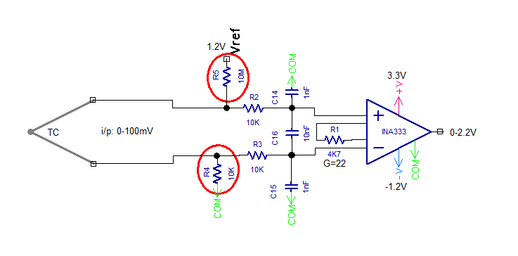
The schematic at www.ti.com/.../TIPD195 for measuring other analog signals (4-20ma, 10v) shows the non-inverting terminal of the INA connected to ground directly.

I am trying to use ina333 for measuring thermocouple in a similar way. When I connect inverting terminal directly to ground instead through a resistor (10K), things are still working fine since the bias current can travel to ground with no problem as shown in TIPD195 schematic.

Please help me answer a few question that come to mind:

1. Is it ok to do this (i.e. shorting R4 to ground) for mV signals such as T/C. Does this affect the noise performance of INA333 because one terminal is connected to ground and common mode signal on the non-inverting terminal becomes a differential signal ?  

2. T/C open detection is being done as shown in the circuit by connecting a high value  pull up resistor (R5). It does create an error that can be corrected while calibration but the resistor does become a source for noise. Is there any other way to detect open connection for INA333 ?

I am new to instrumentation amplifier (INA333) and appreciate your response to these questions. Thank you.
  • Hi Meet,

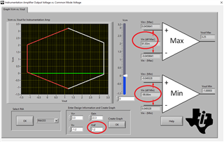
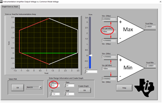
    The output of INA333 for Vdiff=100mV in gain of 22 would be:  Vout = Vref+G*Vdiff = 1.2V+22*100mV =~ 3.4V so this would not work on 3.3V supply.

    The highest thermocouple voltage INA333 could accomodate under your circuit conditions is 92mV - see below.

    If you absolutely need the circuit to work up to Vdiff=100mV, you would have to increase the positve supply to 3.5V - see below.

    For other answers, please see my comments below:

    1. Is it ok to do this (i.e. shorting R4 to ground) for mV signals such as T/C. Does this affect the noise performance of INA333 because one terminal is connected to ground and common mode signal on the non-inverting terminal becomes a differential signal ?  

    How you may reference the thermocouple to ground depends on the thermocouple tip type you use especially for a single supply configuration so it may accomodate signals up to few hundred mV below ground.  Since you use a dual supply, I do not see issue with connecting the negative input directly to ground.


    2. T/C open detection is being done as shown in the circuit by connecting a high value  pull up resistor (R5). It does create an error that can be corrected while calibration but the resistor does become a source for noise. Is there any other way to detect open connection for INA333 ?

    I do not see issue with thermal noise generated by 10M pullup resistor, R5, used for thermocouple open detection. With R5 of 10Mohm and C14 of 1nF cap, the low-pass filter corner frequency is about 15.9Hz.  Thus, the total integrated noise of 400nV/rt-Hz spectral density of 10Mohm resistor will create: Vnoise_total = 400nV/rt-Hz*(15.9Hz*1.57)^.5=~2uvrms.  If further filtring is needed, a low pass filter may be added at the output of the INA333.

  • Hi Marek,

    Thank you very much for your quick reply to my questions.

    I think I may have confused you with Vref. This is the reference for my other circuit and not for INA333. I only attached a part of the circuit as a reference for my circuit. As you may see in the picture, the ref for INA333 is connected COM so that I can get 0-2.2V. I apologize for not numbering the pins for INA333.

    Regarding Q1, thank you for clarifying. I was confused a bit because while reading about instrumentation amplifier, somewhere on the internet it was mentioned that grounding the inverting terminal will prevent the common mode noise (long T/C cables) from reaching to the inverting terminal and the noise on the non-inverting terminal will get converted to differential signal. It also mentioned that the resistor (R4) has to be few hundred times the source impedance which is negligible for T/C. I am taking from your answer that it will not be a problem. It was a concern because I am trying to use in-amp is to get rid of the noise problem we see sometimes in our instruments where we use op amps in non-inverting mode with RC filter.

    For Q2, it is clear from your reply that the arrangement for open T/C detection is ok to use. I will be using a filter before sending the signal to ADC (msp430).

    Again, I really appreciate your clarifications.

    Regards,

    Meet