This thread has been locked.

If you have a related question, please click the "Ask a related question" button in the top right corner. The newly created question will be automatically linked to this question.

TLV4172: Need help for the following circuit.

Part Number: TLV4172

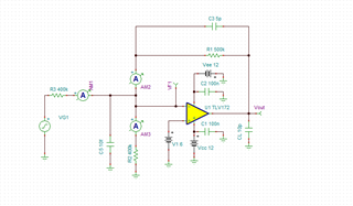
I am trying using integration circuit to detect the variable current which is generated by optical sensitive sensor R3(the sensor resistance is around 500K Ohm), I have measured the sensor and confirmed the sensor functions well (the sensor resistance is around 350K Ohm at 45and the sensor resistance is around 600K Ohm at 22) and also simulation result looks fine too. But in real circuit the output keeps saturated, which should keep changing with variable thermal, please let me know any issues.

Many thanks in advance.
  3323.sboma96a.tsc

  • Hello David,

    In your real circuit what is VG1? If assume it is +12V fixed. This adds current to the inverting input node based on R3 variable resistance. R2 is there to steal current away from the node that should be the close to the typical current of R3. The difference current then flows through R1. So output should be 6V +/- difference current * 500k.  

    Assuming room temp at 22C.  R3=600k (Are you very sure it's is still 600k at 6V supply?). So 10uA in.  R2 = 400k so 15uA out.  R1 should be 5uA in (to balance). VR1 =2.5V , so VOUT is 8.5V ; that is not saturated. Was your sat result -12V or +12V?

    I suspect it is miswired or "R3" does not do what you expected. Last option is ESD damage to one or more components.

    Check your wiring; then check all related pin voltages on TLV4172 (including supply)

    If voltage IN+ > IN- , then output should be +12V (op amp op working) 

    If voltage IN- > IN+ , then output should be -12V (op amp op working)