Part Number: LM9044
Hi,
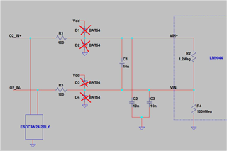
We are using LM9044 for O2 sensor and was working on some options for short to battery and short to gnd protection.
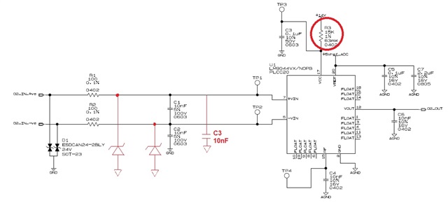
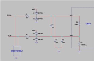
1. Can you please review below scheme for short to battery and short to gnd protection, suggest if changes are required or if there is any other way to implement the same. Since the datasheet mentions use of series resistance from 100 ohm to 1k for input filtering, same resistors can be used for current limiting for clamping diodes?
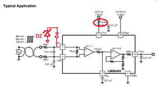
2. On pg 9 of datasheet, for input filtering, it is recommended to use filter for differential mode as well as for common mode but in application circuit, there are only two caps are used one across inv and non-inv lines and other from inv to gnd. Do I need to add one more as shown below or two caps will serve for both common mode and differential mode.
Regards,
Sunney