


Other Parts Discussed in Thread: OPA855
Hello,
i am building TIA with OPA855. Using (and i must use) photodiode with capacity 12pF. Aiming to bandwidth ~100MHz with maximum possible gain (input signal will be in range 0 to 2uA). I expect lot of noise at output. I've build testbed without photodiode. I have 50R/100nF/4k7/12pF as "diode simulation" at input (according to scheme and layout below). Output is routed into end-terminated 50R coax cable. Feedback capacitance (Cf) should be about 0.27pF (if my calculations are correct) and i've used twisted isolated wire to realize feedback capacitor (i've used two 0.4pF 0603 chip capacitors in series before but without success). Input is unconected and holded at ground by onboard 50R.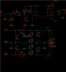
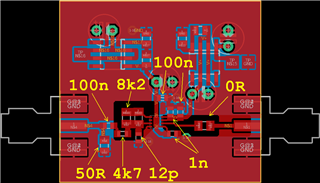
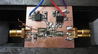
I've made few test with different designs of Cf but every times TIA oscillates. I've made large "gimmick" (like on photo) and unwinding and cutting it slowly to decreasing Cf and measure TIAs output. With large "gimmick" like on photo TIA oscillates at frequency about 970MHz (look at oscilograph below). When i unwind Cf little more oscillations rapidly change to frequency 2.7GHz. With further reduction of Cf frequency slowly rises to about 3Ghz (when gimmick is fully cuted out).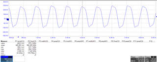

When i try to input current (by lab. generator) and (set input filter at oscilloscope to filter out oscillations) i can see response (slower then expeted).
Am i missing some basics ? Is it possible to build amplifier with that parameters ? And how to achieve stability ?
Thanks to all.
Michal Dudka
