This thread has been locked.

If you have a related question, please click the "Ask a related question" button in the top right corner. The newly created question will be automatically linked to this question.

INA240: Pulse half wave

Guru 55913 points
Part Number: INA240

Hello,

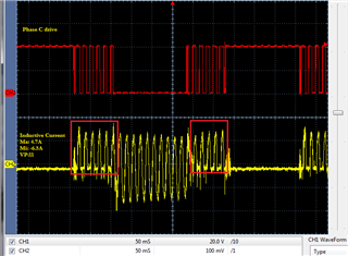
Recently evaluating A1 bidirectional reference as low side monitor of AC inductive 3 phase currents notice odd pulses on the output.  The output has half wave pulses that an inline current clamp does not detect. Please elaborate what these DC pulses result from and why they are on the ends (red boxes)? Why does PWM rejection not clamp half wave pulses when REF1,2 are +1.65v bidirectional current mode? The REF1,2 pins are bus tied with two other INA reference inputs acting in parallel, could that causes 1/2 wave pulses?

It would seem 1/2 wave pulses are detected as unidirectional current flow but REF1,2 are again configured for bidirectional current detection.  

  • Hi GI,

    Unidirectional configuration can be viewed as a special case of bidirectional configuration. Instead of being allowed to move either way, the output can only move in one direction off of the DC level. Other aspects of device operation stay exactly the same. The PWM rejection is not supposed to clamp the output, especially it shouldn’t interfere with normal output.

    To understand the response highlighted by the red boxes, we would need to know the motor control algorithm; understand what the inverter switching sequence which will reveal the current profile. In the absence of this background knowledge however, we can make an educated guess that positive current (indicated by positive half wave @ INA240 output) means the associated phase is forward conducting, and I don’t see anything wrong with it. To the contrary, it would be abnormal if the PWM is switching yet the INA240 output is not.

    The way REF1/2 pins are tied is OK, it is also OK to tie three INA’s together this way.

    Regards, Guang

  • we can make an educated guess that positive current (indicated by positive half wave @ INA240 output) means the associated phase is forward conducting,

    The confusing part being a current clamp never has half wave pulses during the same periods. So it makes no sense for unidirectional shunt current close to 100ms long. The bad part being INA is the feed back loop for generating real time current events that are to produce sinusoidal inductive current.

    Obviously that part of topology is also not working ideally. This seems to be chicken chasing the egg to see where it came from Thinking

  • Hi GI,

    I’m with you on the control loop and therefore the chicken and egg analogy. But in terms of behavior, I’m more convinced that what’s in the red boxes is real. It reflects the real instantaneous motor winding current.

    To prove, you may go through a simple experiment: replace the shunt resistor with another that is 5 or 10x larger (as long as the output is not railed), you should observe the INA240 output increase by the same number of times.

    Regards, Guang

  • you should observe the INA240 output increase by the same number of times.

    Have consider shunt value but for other reasons not related to pulses, rather improving low end precision. The DC pulses just happen to trigger with events CH1 via alternate trigger mode. The DC pulses are perhaps inductive rectified NFET events is another Thinking