This thread has been locked.

If you have a related question, please click the "Ask a related question" button in the top right corner. The newly created question will be automatically linked to this question.

INA121: PSpice Error

Part Number: INA121

Hello:

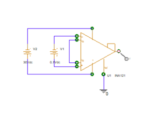
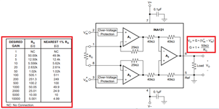
I am trying to run a PSpice simulation using the INA121. PSpice keeps reporting: 


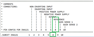
ERROR(ORNET-1017): Unconnected pin, no FLOAT property or FLOAT = e U1 pin '5'

I have it connected to a GRD, so I don't understand why I am getting this error.

  • Hi Joseph,

    Could you share the schematic with us? You may send us an image or draw a picture by hand etc. so that I know your circuit configuration looks like.  

    I imported and converted the INA121's PSpice model in LTSpice, and ran the following circuit which is identical to the Tina model below, I do not see any issues. 

    The following circuit has Gain =1 (Rg input pins are open), Vcm = 1.65V,  Vref = 0V, differential input is +/-1Vpp with Vcc and Vee are configured to +/-5Vdc.

    Please make sure that the following parameters are configured properly, assumed that the pspice model and the corresponding pins are assigned correctly in your simulation tool.

    1. You input Vcm voltage range and voltage supply rails are met the above Vcm requirements. 

    2. Vocm or Vout voltage range is meeting the following requirements. For instance, set the Vcm to the middle of Vcc and Vee range. 

    You may download the Instrumentation Amplifier Output Voltage vs. Common Mode Voltage calculator tool to check out the Vcm requirements per your IA configuration. 

    https://www.ti.com/tool/INA-CMV-CALC

    Best,

    Raymond

  • Hello:

    Thank you for your response. Since you have it working I must be making a newbie mistake. Here what I tried in PSpice:

  • Hi Joseph,

    Here are couple issues you need to resolve with INA121:

    1. Since you are using single supply rail of 30V, you need to take care of input Vcm mode voltage. In the example below, I placed at approx. mid point of Vcc voltage of 15Vdc. 

    2. You should not short Rg pins, which it implies extreme high gains (50001 V/V) from the transfer function. 

    3. Since this is single supply rail, you need to elevate Vref to somewhere in the mid point of Vcc. I configured Vref at 10Vdc. 

    INA121 06092021B.TSC

    Please download the calculator tool that I mentioned from the previous reply, and it will help you to check out the Vcm input and Vref ranges. 

    If you have additional questions, please let me know. 

    Best,

    Raymond

  • Hello

    I cant find info on what the green circles are, I thought they meant a connection point but you design didn't have these?

    Would you please share the model you ran?

    When I try to run the example model for the INA121 I get msg that model already opened but I don't see where etc?

  • Hi Joseph,

    This is part of PSpice model that is downloaded from INA121 site. Pin8 is configured as the Vref pin. 

    https://www.ti.com/product/INA121#design-development

    INA121.LIB

    I converted the INA121 symbol from the PSpice. If you still have the modeling pin assignment issues, please perform "friendship" request via the E2E site. 

    Best,

    Raymond

  • Thanks Raymond! Sorry for tardy thankyou.