A related question is a question created from another question. When the related question is created, it will be automatically linked to the original question.
If you have a related question, please click the "Ask a related question" button in the top right corner. The newly created question will be automatically linked to this question.
Part Number: OPA2333 Other Parts Discussed in Thread: LM2775
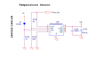
Hi Team, I'm designing a temperature sensor using a diode and the opamp OPA2333. The diode used can be 1N6642/1N4148 Below is my circuit. is there any problem with the design. Please correct me if I'm wrong
The output will be connected to a 3.3V logic controller. Also, I'm using the same opamp in the circuit as a summer configuration.
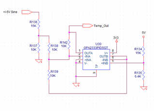
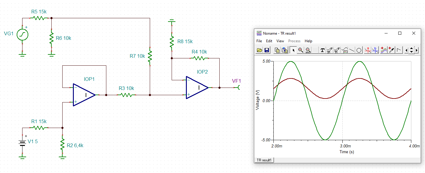
The +5V is from a boost converter (LM2775). A voltage divider is set to a voltage of about 1.5V. My input signal is a sine wave of amplitude +/-5V and frequency 10KHz. Another voltage divider is used to make the input voltage to a level of around +/-1.5V. This voltage divider is in reference to the ground. so there will be a shift for my signal. My doubt is since my reference voltage is 1.5V from a voltage divider, and the entire system is powered from LM2775, will it arise any problem. Also, I think the voltage divider will not be stable due to the sine wave at its output, so it may difficult to get proper output.
In the circuit given 5V is the output of our LM2775 IC. A voltage divider is set to get a voltage of 1.5V using resistors 15K and 6.4K and the 1.5V thus generated followed by a buffer (op-amp B) is fed to as the reference voltage of an adder circuit at the op-amp A. My input signal is a +/-5V sine signal and a voltage divider is set using resistors R136 and R137. The adder is the op-amp A. My doubts are 1). Since LM2775 is a charge pump will my incoming signal affect the performance of my 5V supply rail?. I hope since we have a buffer, that won't be an issue. 2). Is this the correct method for an adder circuit?. 3). I want my signal at Temp_out net at a range of 0-3V, Is this the correct design for that?. Please correct me if I'm wrong
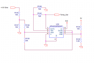
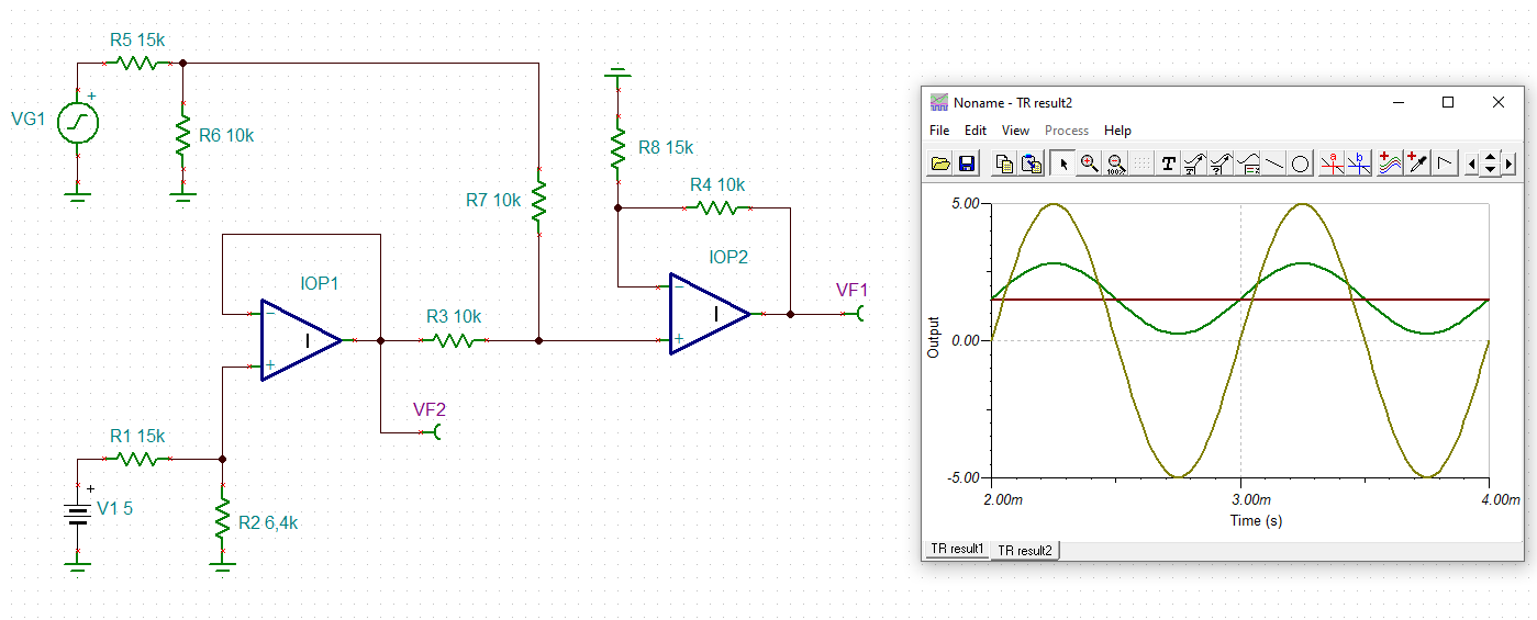
Hi Kai, Thank you for your reply. I've updated the circuit.
My doubts are 1). Since LM2775 is a charge pump will my incoming signal affect the performance of my 5V supply rail?. I hope since we have a buffer, that won't be an issue. 2). Is this the correct method for an adder circuit?. 3). I want my signal at Temp_out net at a range of 0-3V, Is this the correct design for that?. 4). I have a similar adder circuit in the same system, Can I use the same buffer (op-amp B) there also?. Or will it affect my input signals?. Please correct me if I'm wrong
The op amp is powered from th e 5V. my bad, I labelled it as 3.3v.
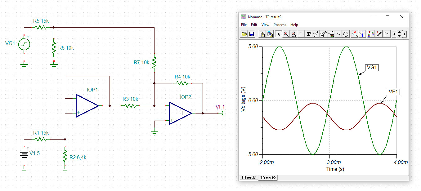
In the simulation circuit you provided, if we measure the signal at the output of buffer op1 the output is not steady due to the sine signal. So can I use the same buffer for another adder circuit.