This thread has been locked.

If you have a related question, please click the "Ask a related question" button in the top right corner. The newly created question will be automatically linked to this question.

INA301: INA301 Input Impendance

Part Number: INA301
Other Parts Discussed in Thread: INA228, INA229, INA190, INA239, INA200, INA186

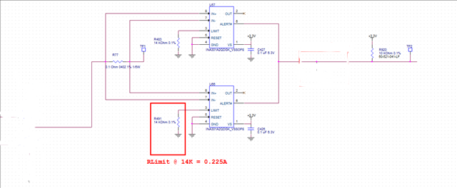
The measured impedance of both comparator inputs is about 50K ohms. Since I didn’t find anything relevant concerning the input impedance
In the data sheet, I assumed it was in the order of Mohms. I don’t have any issues for current sensing, however the relatively low impedance on the transceiver line I’m driving (TP1)
Is affecting badly my software enabled PU resistor. It is actually acting as a voltage divider of almost 50% with my actual 27K ohms PU. I’m aware that I could drop the resistor value to a more “neglectible”
Value, however my power budget for this design won’t allow me to have too much power dissipated with those PU resistors.

I have been thinking of a workaround, like adding a series resistor on the inputs to raise the impedance , however I’m afraid it would affect the precision of the current sensing INA301.

My question goes as follow: Is there any IC with a known input impedance that would be much higher impedance while using the same topology as provided with the above screenshot?
If not, do you see any workaround that could possibly patch the issue I’m having according to the following specs :

Nominal voltage on transceiver line : 28V
Actual PU resistor : 27K ohms — power budget is fine but acts as a voltage divider with INA301 input impedances
“Patch” PU resistor : 3K ohms 1/3W 0603 — drives too much current for design
Trip current on INA inputs : 0.225 mA

Regards

  • Carl,

    The input resistance of a current sense amplifier have higher IB than most amplifiers.  For this device each input has 120µA each pin and it is not recommended to add series resistance.  This input bias current also changes with the common mode voltage as seen in figure 17 in the datasheet.  This input structure allows for the VCM voltage to be above Vsupply of the current sense amplifier but the draw back is the input bias current.  Normally for larger current this will not impact the measurements but once measurements need to be lower they become a larger part of the error.  We have some current sense amplifiers with lower IB currents but none with comparators.  The other draw back for some of these is the bandwidth which for most applications that require a comparator usually need high speed.

    The INA229/INA228 are digital parts that have low IB and can measure with ADC down to 50µS conversion time.  This may not work for you but that is an options.  We do have some other digital parts that have less resolution with the 50µs conversion time as well.  These device have limit registers where you can program the limits current.

    The INA190 has low IB but the it does not have a comparator and the bandwidth of these device is lower than that of the INA301.

  • Hi Javier,

    Thank you for your quick reply. I realize there isn’t much work around according to your answer. Now let’s say I want to use one of the current sense IC with I2C.
    Do you see any problem configuring 128 devices in a parallel topology (writing only, same address)  ? The purpose would be to use over current alarm asserting only (same config for all).
    Or else, is there any problem using a daisy chained SPI interface i.e using the INA239?

    Regards

  • Hello Carl,

    I need to look into this.  I am not sure if there would be any issue.

  • Thank you Javier.

    The INA200 could potentially replace the INA301 since it is pin compatible. IB is 10x lower than INA301, can you confirm that it could resolve my issue mentioned above? 

  • Carl,

    The VOS of the INA200 is 2.5mV(max) for the gain of 200.  So for your Rshunt of 0.1Ω that is equal to an error of 25mA from the current sense amplifier VOS before adding the IB current of 16µA.  Other error sources would be the divider required to get the correct trip point.

    As for the digital option we do not have daisy chain capabilities and you can write to multiple I2C devices as long as the timing specifications are still meet.  Keep in mind that the accuracy is much higher on the digital devices I mentioned and they have lower IB but the accuracy will drop as you lower the conversion time.

    What is the speed you need this done at.  Can you use an accurate CSA with a comparator?  Like the INA186 or the INA190.