This thread has been locked.

If you have a related question, please click the "Ask a related question" button in the top right corner. The newly created question will be automatically linked to this question.

PGA204: How to configure IA for best results with high source impedance.

Part Number: PGA204
Other Parts Discussed in Thread: OPA391, LMC660, LMP7721, OPA3S328

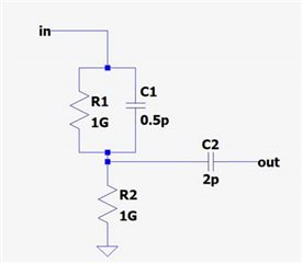
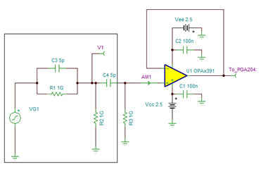
I am attempting to use the PGA204 Instrumentation amplifier as a unity gain buffer between a high source impedance and an NI-DAQ, but have so far been unable to collect a reasonable measurement. I have attached a schematic of my circuit below.  The Input is ~100mV, C1=5p, C2=5p, the output is being fed to the input terminal on the PGA204.  I am hoping to be able to resolve a small change (1-5%) in the input voltage.  Can somebody please advise the proper configuration of the PGA204 for this purpose?  In particular, what are appropriate values for the input bias current resistors? 

  • Hello Jeremy,

    I have a couple of questions:

    What is the signal frequency range of interest and what kind of sensor or source is driving the PGA204? Please let me know the common-mode voltage of the source signal with respect to the PGA204 local ground and what is the output impedance of the source. Are you attempting to AC couple the inputs, or why does the application require C1=5pF and C2=5pF?

    The PGA input bias current path resistors are required for applications where the sensor or source floats, where the source does not offer an inherent path for the input bias current. In general, the input bias current resistors are chosen to be relatively high-impedance when compared to the source output impedance in order to not load the source.  The current return path resistor(s) value depends on the output impedance of the source; but there may be other considerations.  For example, on an AC coupled signal application, the input current path resistors interact with the DC blocking capacitors and play a role on the corner frequency of the DC blocking high pass filter.

    Thank you and Regards,

    Luis

  • Hi Luis,

    The signal frequency range of interest is <1kHz. 

    It is a proprietary biosensor modelled by the circuit I have attached above w/ R1=R2=1G and C1=C2=5p.  

    C1=C2=5p is a test condition for the circuit, as the specific values of these parameters is not yet known in the real biosensor.

    In my setup I have tied the local GND of the amplifier to A- In to the GND in the above circuit.

    Jeremy

  • Hi Jeremy,

    The PGA204 has an input impedance of 10GOhm and input differential and input common-mode capacitance of 6pF. The typical input bias current of the PGA204 is ~500pA.  Using the required PGA input DC current path resistors will create a high pass filter while interacting with the sensor output 5pF capacitance. When using very large current path resistors, in the 10s or 100-MOhm range, the DC path resistor(s) will produce errors due to the ~500pA bias current.  

    One possibility would be to buffer the sensor with a low input bias current, low input capacitance operational amplifier.  If the ~100mV sensor signal is referred to GND, set at a relatively low common-mode voltage, buffering the sensor with a low bias current amplifier such as the OPA391 could be a possibility.  The OPA391 is a 5.5V operational amplifier, with an input bias current of ~0.8pA max at 25C, and the input differential and common mode capacitance is low at 1pF. 

    What is the lowest range of frequency of interest? 

    Let me know if using the OPA391 would be something that could be considered on your application.

    Thank you and Regards,

    Luis

    TINA SPICE:

    5826.OPA391_and_sensor.TSC

  • Hi Luis,

    Thank you for this, it is helpful.

    Vin is likely to be DC step voltages varying by ~1mV every few ms.  I would like to be able to sense this change at Vout.

    I am not necessarily married to the PGA204, I am looking a buffer to a DAQ.  Something with a higher input impedance would be nice.  It looks like the OPA391 you have suggested has a 1TOhm typical input impedance.  I have also looked into the LMC660, would this be a suitable component?  Can you please recommend other TI components that may work for this circuit?

    Thanks,
    Jeremy

  • Hi Jeremy,

    If you are looking for ultra-low leakage current amplifiers, low leakage, the LMP7721 is another option.

    The OPA3S328 is a device that has relative low input bias current 0.2pA typ, <10pA over temp (not as low as the LMP7721). The device incorporates switches and could be used to build a programmable gain amplifier. The OPA3S328 integrates analog switches could useful to select different voltage gains. The second-stage amplifier buffers the programmable gain stage using Kelvin sense connections to eliminate errors due to the switch on-resistance, switch resistance drift and non=-linearity. The device has plenty of bandwidth and low output impedance so will be able to drive ADCs.  See figure below.

    Thank you and Regards,

    Luis

  • HI Jeremy,

    Please see below the OPA3S328 configured on a programmable gain amplifier configuration. 

    The OPA3S328 input impedance is high since it is intended for transimpedance amplifier applications (but not as high as the ultra low leakage LMP7721 or LMC660), but the device offers relative low input bias current.  If you are interested on the OPA3S328 let me know and I can quickly look in simulation and see how the impedance interacts with the output impedance of your sensor.

    Thank you and Regards,

    Luis 

  • Hi Luis,

    Thank you for all of this info, it has been helpful.  Can you please suggest a vendor for the OPA3S328 - I was unable to find this part on digikey or Mouser.

    Also, can you please advise as to why I might prefer the LMP7721 vs the OPA391 vs the OPA3S328 for this application?

    Jeremy

  • Hi Jeremy,

    The OPA3S328 is a new device in preview, samples are available at TI.com.  The device is expected to fully release to market third quarter this year (2021).  You may order samples on the link below:

    https://www.ti.com/product/OPA3S328#order-quality

    The OPA391 offers high impedance, 1TΩ common-mode and 0.1GΩ differential impedance, low input capacitance, 1pF (differential and common-mode) and very low input bias current of 10fA at room temperature, 5pA from 0C to +85C.  The offset error is relatively low at ±45μV.

    The LMP7721 offers lowest input bias current over temperature, 900fA from -40C to +85C.  If your sensor / op-amp will be exposed to temperature changes, and the sensor is sensitive to input bias current in the pico-amps range, the LMP7721 is the best choice from the input bias current perspective.

    The OPA3S328 has a typical low input bias current of 200fA, and max input bias current 10pA max.  The offset error of the OPA3S328 is the lowest at 25µV max at room.  The input impedance is lower than the OPA391 at 1GΩ common-mode and 100MΩ differential impedance.

    If you are planning to use different gains, the OPA3S328 is a good choice; offering relatively high input impedance and integrating switches to set up the amplifier in non-inverting configuration with different gains. Otherwise the OPA391 or LMP7721offer higher input impedance, lower input bias current.

    Thank you and Regards,

    Luis