This thread has been locked.

If you have a related question, please click the "Ask a related question" button in the top right corner. The newly created question will be automatically linked to this question.

LM2903B: design help

Part Number: LM2903B
Other Parts Discussed in Thread: LM2903, TINA-TI

Hi all

I wanted to know, if its possible to set the hysteresis of the comparator LM2903B in the kind of way i did it? From the transition of Low to High, the output becomes high and the MOSFET conducts and the voltage at the inverting input of the LM2903 drops a little.

i am asking because in the simulation i saw Oscillations when the output goes from low to high. Now the question is: Is it just a simulation issue or a real world problem.

  • Hi Lidong,

    the idea of using a positive feedback loop to add an hysteresis is to instantaneously shift the potential at the +input of comparator. Introducing a time delay by the turn-on time of MOSFET would be counter-productive. It makes no difference that the "hysteresis" is applied to the -input here. So what happens in the simu can happen in the real circuit as well.

    Another issue is charge injection. During the switching a small charge is injected into the gate source capacitance resulting in a current spike running through the two resistors at -input of comparator and causing an unwanted voltage drop. This voltage drop adds to the desired potential shift and can minder the hysteresis, if being of wrong polarity. In the worst case the whole circuit can oscillate.

    Kai

  • Thanks Kai, I agree with your comments.

    Hi Lidong,

    I am going to work on an implementation that does not require the MOSFET and should take care of the oscillations. I am going to assume that you are powering the LM2903 with 24V supply, so let me know if that is not the case. I do want to caution you that the common mode voltage range is limited to Vcc - 2V and that one of the pins needs to be below this threshold for a valid output. 

  • Hi Lidong,

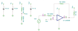
    I made a non-inverting circuit with hysteresis that approximates the hysteretic window that your circuit was implementing with a simulated Vth of 12.53V and a Vtl of 7.65V. This setup should not have the oscillation problems that you were simulating with your circuit. I am attaching a Tina-TI .tsc file so that you can modify it to better suit your needs if required. Note that the values of R2 and R3 relative to the pull up resistor matter and if the ratio is reduced too much, then the output will be pulled to a value greater than 3.3V. With the current setup, the maximum simulated output is 3.4V.

     LM393B_reference_design.TSC

  • Thanks Izak, this looks great.

    Lidong, I hope this provides a good alternative to your original proposal.

    Chuck