This thread has been locked.

If you have a related question, please click the "Ask a related question" button in the top right corner. The newly created question will be automatically linked to this question.

INA145: FCT failed

Part Number: INA145

We find INA145UA/2K5 ,DC2042 have about 32% failed in FCT, the detail information as below :

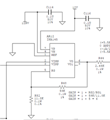
For component level, we did as below: (Designed Gain is as below snapshot, 59K: 1%, 11.8K: 0.1%)

OK Board: pin2~3:-0.0209 VDC, pin6:-0.1259VDC, Gain=6.0239

Failed Board: pin2~3:-0.0208 VDC, pin6:-0.1177 VDC, Gain=5.6586

Pin2/pin3 input about -14.0X VDC.


RG2:59.121K

RG1:11.797K

RG2/RG1=5.0115


Power with +/-12VDC


  • Hi Zoe,

    hhm, you apply -14V to pin 2 and pin 3? What does the following mean then?

    pin2~3:-0.0209 VDC

    Kai

  • Hi Zoe,

    I simulated your schematic and the simulation seems to agree with your measured data in a good unit. 

    INA145 E2E 06252021.TSC

    Can you provide us with more information at INA145's input and output load?

    1. Please check the circuit's input impedance or provide us with full schematic. 

    2. OK Board: pin2~3:-0.0209 VDC, pin6:-0.1259VDC, Gain=6.0239. Failed Board: pin2~3:-0.0208 VDC, pin6:-0.1177 VDC, Gain=5.6586

    Can you see the "failed" board has different offset voltage, Vos? The difference between Pass and Fail board in only approx. 125.9mV - 117.7mV = 8.2mV, which the Vos (RTI) is approx. 1.37mV. INA145UA's  Vos (RTI) can be up to +/-1mV in the worst case at 25C. 

    3. Possible parasitic effects on PCB boards (speculation). Please make sure that the boards are clean and have gone through ultrasonic cleaning and washing process. 

    4. What is the INA145's load? The schematic is shown 2.49kΩ in series with INA145's output. 

    Please provide us with more data to troubleshoot the issues. 

    Best,

    Raymond

  • Hi Zoe,

    I am going to close this inquiry, since we have made contact via our internal email. 

    Thanks,

    Raymond