Because of the holidays, TI E2E™ design support forum responses will be delayed from Dec. 25 through Jan. 2. Thank you for your patience.

This thread has been locked.

If you have a related question, please click the "Ask a related question" button in the top right corner. The newly created question will be automatically linked to this question.

OPA2350: op amp with thermal pad, best decoupling capacitor placement for Sallen Key LPF

Part Number: OPA2350

Hello,

I have a Sallen key 2nd order filter with OPA2350 8VSSOP and 0603 0.1uF cap that is passing through noise from the switching power supply. The noise looks like a few 100 MHz cycles that happen 40 us. I was thinking to improve for the next revision the layout. This circuit goes to a piezo in a laser circuit so I need low noise.

I have 3 main questions:

Q1) I was thinking for a low noise op amp with thermal pad, with the goal of having even better grounding and shorter connection to the decoupling cap.  I only get 17 dual op amp parts with these packages, which is not that much. Am I missing some packages that should have thermal pads? What packages should I look for?

https://www.ti.com/amplifier-circuit/op-amps/products.html#p480=2;2&~p78=In;Out&o7=General-purpose%20op%20amps&p2954=Power%20Package;QFN;SO%20PowerPAD;SON;VSON;WQFN;WSON

Q2) Could someone recommend a good layout from an eval board or app note?

Q3) Should I switch over to a single channel op amp for better results in layout and parts selection?

I have 6 layer board with L1=top signal, L2=ground, L3= analog power with a section of 3.3V below the op amp).

I used this circuit with the layout.
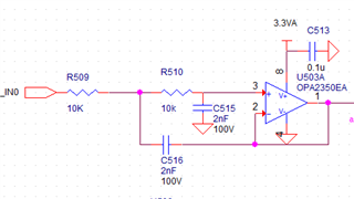
R509 connection to in0 is ripped out.
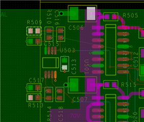
I just left the capacitor on the side with vias to 3.3V and ground. Some of that idea came from Howard Johnson's site at:

http://www.sigcon.com/Pubs/news/9_07.htm

Decoupling cap impedance in old circuit with Yageo cap.
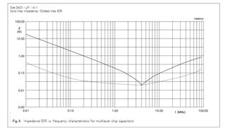
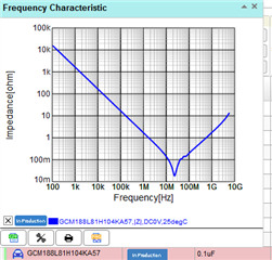
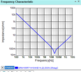
I will change to Murata 0603 or 0402.

https://ds.murata.co.jp/simsurfing/mlcc.html?lcid=en-us

Murata 0603
Murata 0402
Thanks,

Frank

  • Hey Frank, right at the beginning you said your supply feedthru was 100MHz? Sounds like you need better supply decoupling even if the app and amp are much slower, 

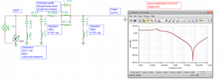
    I had pursued a thorough decoupling model some years back using a pi filter on the supply - this included a ferrite bead between your 0.1uF and an X2Y right at the device pins. Here is that file, not maybe exactly what you need but a start. This is the source impedance sim looking out of the DUT supply pin, 

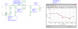
    And then looking forward from the power supply the DUT supply pin, what I don't have in this is the apparent load looking into the DUT supply pin, but -100dBc at 100MHz might help your issue if I understand it correctly, 

    And this last file, 

    Murata BLM21AG102SN1 with X2Y for power supply filtering forward filtering.TSC

  • Hello Michael,

    I still need to investigate best rooting. The X2Y capacitor has super tiny inductance. The PCB connections take the nice schematic and add inductance. Any kind of layout info would be helpful. Thanks,

    Frank

  • Hi Frank,

    Michael's solution is spot on and sage advice about adding the supply line pi-filter at the OPA2350 supply pin.

    Have a look at the information on the X2Y capacitors manufacturer's websites. They may provide information about optimizing the X2Y PCB layout.

    See if you can access the "Electromagnetic Compatibility Engineering" book by Henry W. Ott. Chapters 16 and 17 provide some of the most useful information I have found about good PC board design and layout practices regarding RF.

    Regards, Thomas

    Precision Amplifiers Applications Engineering

  • Hello Thomas,

    >Michael's solution is spot on and sage advice about adding the supply line pi-filter at the OPA2350 supply pin.

    I agree to the pi filter completely.

    We have a different 110V to 12VDC adapter and the power supply common mode differential mode filtering circuit present before the multiple regulators is under redesign.

    >See if you can access the "Electromagnetic Compatibility Engineering" book by Henry W. Ott. Chapters 16 and 17 

    I have a copy of that book at home. I will check those chapters.

    Frank

  • Hi Frank,

    if the 100MHz EMI is actually coming from the switching power supply, then you should suppress this EMI right at the source and not "at the end of the road" at the OPAmp. Why? Each decoupling cap being directly connected to this noisy supply voltage will inject an insane portion of this 100MHz EMI directly into signal ground and will contaminate it with EMI. And even with an individual supply voltage decoupling Pi-filter at your OPAmp of interest you will suffer from this 100MHz EMI because signal ground is already contaminated with it. The 100MHz EMI is inseparably linked with your wanted signal then.

    So mount a suited Pi-filter directly at the source before routing the supply voltage to the circuit. Keep in mind that when a heavy DC current is flowing out of the power supply (and through the ferrite bead !) a standard non-high-current ferrite bead might go into magentic saturation and loose nearly all of its inductance. In this case take a high-current ferrite bead even if this offers only about 100R impedance at 100MHz. Built in a standard Pi-filter the dampening at 100MHz will still be enormous and -eventually- you might no longer need individual Pi-filters at every OPAmp or they need at least not be any longer high performance Pi-filters.

    Pi-filters are extremely helpful. But more important than using a brilliant high-performance Pi-filter is to use the Pi-filter at all, even if it is non-ideal. Or by other words, more important than using the X2Y cap is using the Pi-filter. The X2Y cap is the cherry on top of the cake. But don't forget the cake Relaxed

    Another issue is the Sallen-Key low pass filter itself. It's a known fact that active second order Sallen-Key low pass filters appear to be transparent for very high frequencies. So if very high frequencies are present in your signal, take a third order Sallen-Key low pass filter with the first RC-element being pure passive. This can extremely enhance the dampening at the very highest frequencies.

    Kai