This thread has been locked.

If you have a related question, please click the "Ask a related question" button in the top right corner. The newly created question will be automatically linked to this question.

OPA3690: Video buffer

Part Number: OPA3690
Other Parts Discussed in Thread: OPA690, OPA3691

Hi,

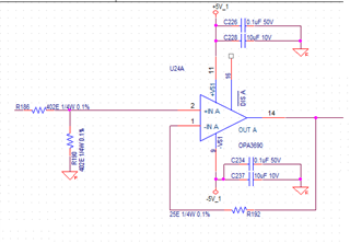
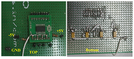
I am testing OPA3690 at bench level as simple Voltage follower with 25 ohm series resistor as in application note. Powered by +5 and -5V dual supply . ( Initially tested in prototype Video board with same configuration and no load, the IC was dissipating too much heat above70 degree Celsius at room temperature)

Each opamp is taking 40mA current at 0V input. all 3 around 100mA current without load. As per the datasheet it should be 16mA current max.

The same I tested with OPA690 it is fine, the temperature increases by only 4 degree Celsius.

Please suggest what could be the reason and how reduce the current or dissipation of the IC.

Praveen

  • Hi Praveen,

    exactly like in figure 46 of datasheet? With grounded input and 50R output resistor? What power supply decoupling? All supply pins decoupled?

    I always use Pi-filters for the supply voltage decoupling. Two 2.2...4.7µF caps with 4.7...22R between, forming a Pi. Sometimes I even put a ferrite bead in series to the 4.7...22R resistor. Depends a bit on the load of OPAmp.

    Please show an exact schematic or your circuit, the layout and a photo of your setup.

    Kai

  • Hi Kai,

    Connected as per the Schematic is as attached. 

    Decoupling is done with 01uf and 10uf . I didn't use any pi filter. 402 ohm input resistor divider is connected and tested by removing input shunt resistor also. the result is same.

    The same I tested with OPA3691 current feed back amplifier. The output ripple is high otherwise current and thermal aspects are ok.( feed back resister is 499 ohm as suggested otherwise all configuration is as OPA3690)

    Regards,

    Praveen

  • you need a load,, and don't probe directly on output pins if you want to stay out of oscillations. 

  • Hi Michael,

    Actually I am using OPA3690. For circuit testing purpose tested with OPA3691( since both are built to print). The actual  problem is OPA3690 with load(75 Ohm) /without load  using supply current  is high. So the IC thermally getting heated. I think IC is in unstable at some point I am not getting the reason. As I told before OPA690 also does not have any problem and OPA3691 also ok. If bot ICs are stable with the circuit why OPA3690 is misbehaving. 

    Regards,

    Praveen Kumar M

  • Perhaps you could look at the output pin to see if there is an oscillation present?

  • Hi Praveen,

    you didn't answer all of my questions and you didn't post a photo of your layout and setup either. So I try again...

    1. Have you connected all supply voltage pins of the OPA3690 to the supply voltages? You must connect pin 9, pin 11, pin 13 and pin 15 to the supply voltages. And you must mount decoupling caps to all these pins.

    2. When you connect the supply voltages to the OPA3690 from an external power supply unit, you should enhance the supply voltage decoupling. So use Pi-filters instead of single caps. I repeat what I have written earlier:

    I always use Pi-filters for the supply voltage decoupling. Two 2.2...4.7µF caps with 4.7...22R between, forming a Pi. Sometimes I even put a ferrite bead in series to the 4.7...22R resistor. Depends a bit on the load of OPAmp.

    3. You should mount a 50R resistor in series to the input, as shown in figure 45 of datasheet. Mount this 50R resistor directly at the input pin.

    4. The same is true at the output. Mount a 50R isolation resistor in series to the output. Mount this 50R resistor directly at the output pin. Also see figure 30 of datasheet. Never directly touch the output pin with the scope probe. Always touch it behind the isolation resistor.

    5. The datasheet recommends to use a parallel circuit of an 6.8µF electrolytic cap and a 100nF ceramic cap for the supply voltage decoupling. The reason for this suggestion is, that the parallel circuit profits from the non-vanishing ESR of electrolytic cap. You will get this impedance then:

    When taking two ceramic caps, on the other hand, you will get this impedance:

    And when mounting the 10µF cap 10mm away from the 100nF cap, you even might get this:

    praveen_opa3690.TSC

    The crucial point here is, that right at the frequency where the impedance peak occurs the circuit can oscillate.

    Kai 

  • Hi Kai,

    Thank you for elaborated explanation. I am testing IC with General purpose SOIC PCB adaptor Board. Tested all possibilities in the board.

    1. Have you connected all supply voltage pins of the OPA3690 to the supply voltages? You must connect pin 9, pin 11, pin 13 and pin 15 to the supply voltages. And you must mount decoupling caps to all these pins.

    Yes, all pins are connected to Power and 100nF capacitor is connected to all power pins. One 4.7uf Tantalum capacitor for +5V and -5V  connected and tested. DIS# pins are Open.

    The power supply with (+5V and -5V)  current consumption is 100mA.

    2. When you connect the supply voltages to the OPA3690 from an external power supply unit, you should enhance the supply voltage decoupling. So use Pi-filters instead of single caps. I repeat what I have written earlier:

    Yes, Tested with 4.7uF 22 ohm 4.7uF pi filter the result is same. Current is reduced to 75mA. Heat dissipation is also reduced but the output is unstable. The input is applied from battery powered calibrator. (Planning to test with customized PCB ) 

    3. You should mount a 50R resistor in series to the input, as shown in figure 45 of datasheet. Mount this 50R resistor directly at the input pin.

    Yes, Point 1 and 2 is tested with 50 ohm input and output series resistor

    4. The same is true at the output. Mount a 50R isolation resistor in series to the output. Mount this 50R resistor directly at the output pin. Also see figure 30 of datasheet. Never directly touch the output pin with the scope probe. Always touch it behind the isolation resistor.

    Yes, Point 1 and 2 is tested with 50 ohm input and output series resistor


    I am doing customized board for the OPA3690 instead of testing in general purpose board. Thank you for your support.

  • Hi Praveen,

    can you post a photo showing the PCB with the components, please?

    Kai

  • You say a general purpose SOIC PCB adaptor board? Surely, you are not socketing this>150Mhz device? 

  • Hi Kai,

    Sorry for the late replay,

    Test Case 1: 

    Board with 6.8uF ceramic capacitor and without pi filter. It is a custom board with 6 layer stack up and proper ground layers.

    Highlighted portion is OPA3690,

    a. Initially tested with this board problem faced heating and high current issue as discussed before (100mA without load and with 75 ohm load, 50 Ohm series resistor also added).

    b. Same test is done with with OPA3691 and OPA690  it was OK

    Test Case 2: 

    Tested with General purpose board by incorporating the Tantalum capacitors(4.7uF, 100nf ceramic capacitors  and pi filter as suggested.

    Regards,

    Praveen 

  • Hello Praveen,

       Thank you for sharing the layout with us. For test case 1, you replaced OPA3690 with OPA3691 on the same exact board, and OPA3691 had normal operation + quiescent current, but OPA3690 had normal operation but at a much higher quiescent current? For test case 2, did you try both OPA3691 and OPA3690 with the same results as in test case 1?

    Thank you,
    Sima

  • Hi Sima Jalaleddine,

    In test case 1, I can not tell exactly it was working normal, there was a some noise I can see in RGB video signal but it may be due to high heat dissipation also.

    In second case We did not check that since it was already working in previous board. I will check and get back to you.

    Regards,

    Praveen 

  • Hi Praveen,

       For test case 1, how about for OPA3691 with normal quiescent current? Is it working correctly for that part? 

       For second case, this would be helpful to make sure the new board works as intended as in the previous board. 

    Thank you,

    Sima 

  • Hi Praveen,

    please don't feel offended, but your setup shown in the photo is totally inappropriate for handling a 500MHz OPAmp. With such a setup you could test a 1MHz OPAmp, but not a 500MHz OPAmp and certainly not a triple 500MHz OPAmp.

    The decoupling caps and the other components must be referenced to a solid ground plane.

    Why not adopting the recommended layout of EVM?

    Kai

  • Hi Kai,

    I agree that test case 2 , just I did for testing, since it was not working in 1test case.

    In test case-1 it has solid ground plane  for power and ground. Only ceramic 6.8uF was used , I replaced ( externally soldered since PAD Package 0805) and tested, as I told it is a 4 layer board with 1 solid power and ground layer. It also has Pi filter near power source for filtering (Near Power source approximately 5 inches away form IC ).

    One difference I am seeing with evaluation board is ground is etched in the solid plane below the IC. I am getting new Testing PCB,  I will check and I will get back to you if any further information is needed.

    Regards,

    Praveen Kumar

  • Hi Praveen,

    this is done to minimize the stray capacitance and to make room for those components which cannot be mounted on the top side.

    If you have issues making the OPA3690 run stably, I would strongly recommend to take three OPA690 instead of one OPA3690. I don't like the huge package of OPA3690 and the long internal connections to the input, output and supply voltage pins. And there's this huge gap in the ground plane to me made with the OPA3690. Using three single OPAmps instead of this fat old dino tripple OPAmp is so much simplier Relaxed

    Kai