Part Number: INA321
Other Parts Discussed in Thread: LMP7721, REF2030, , REF70
Hi, TI.
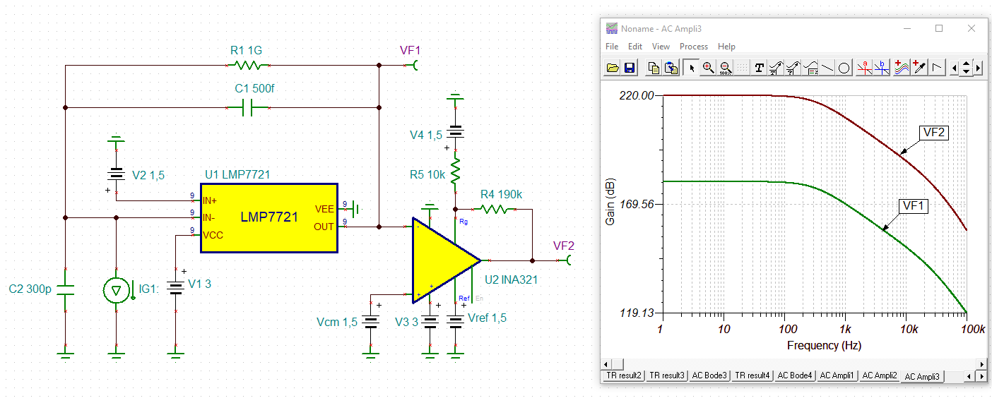
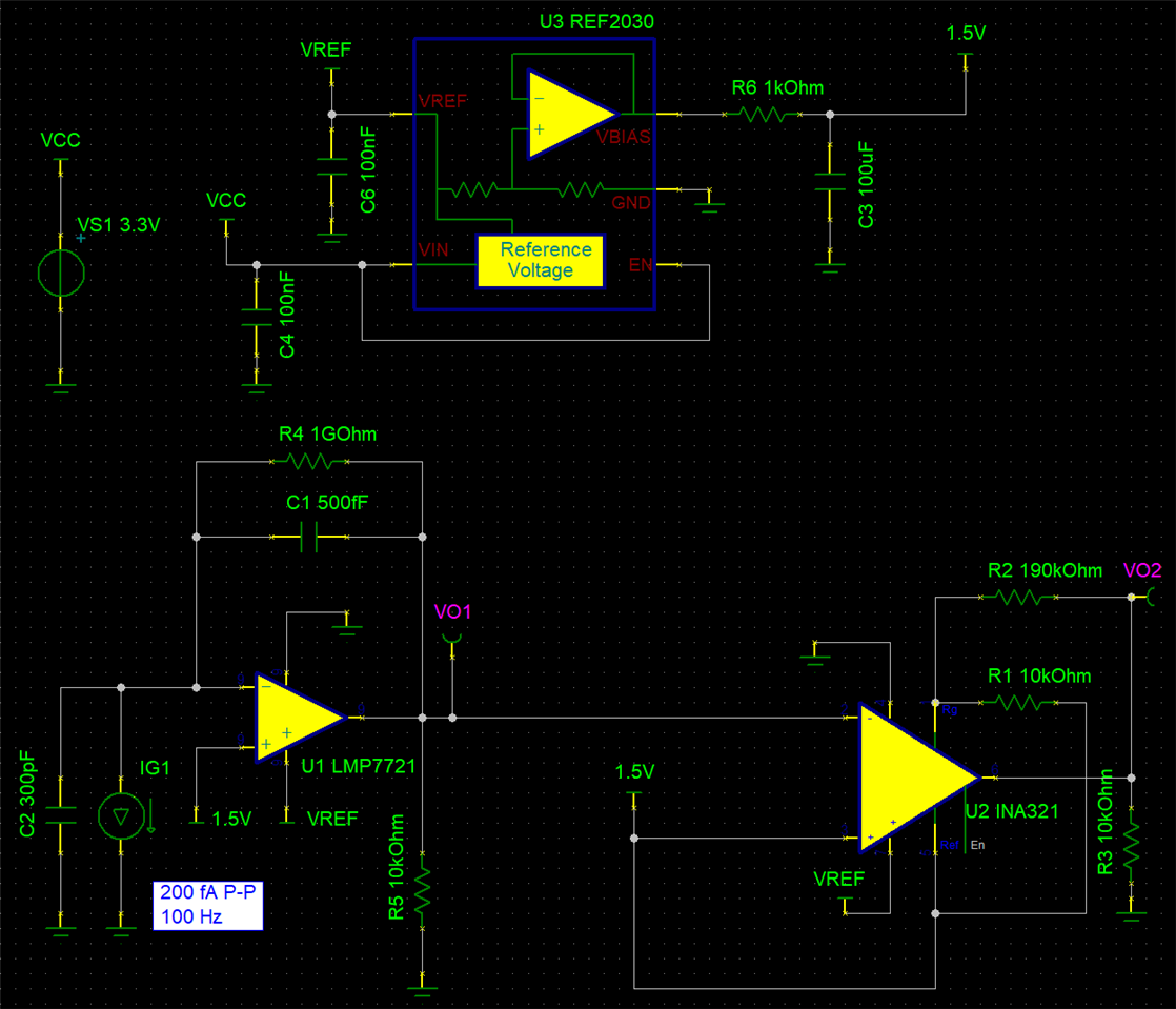
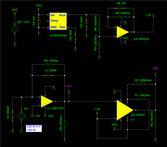
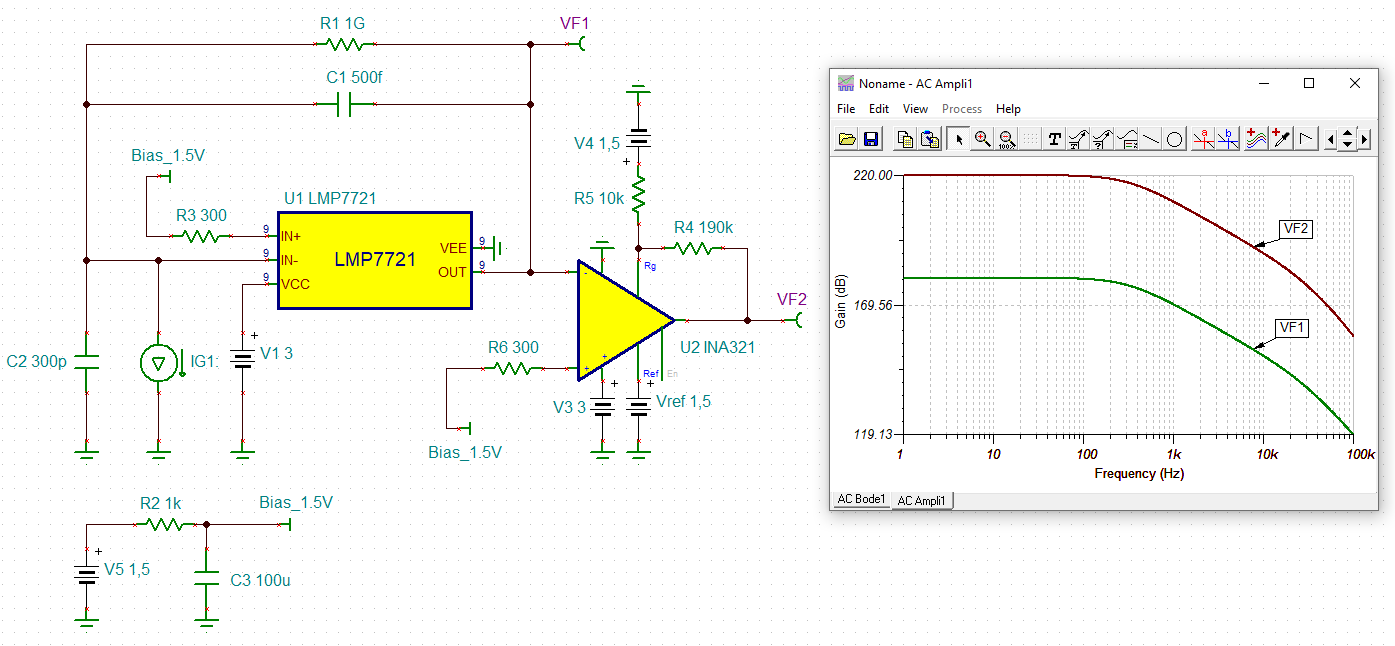
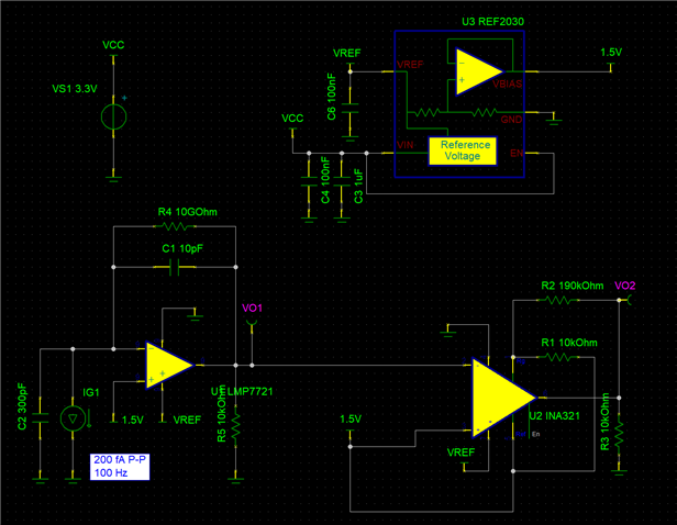
I designed a trans-impedance amplifier circuit using a LMP7721, INA321 and REF2030.
The INA321 was used to amplify the fluctuating voltage signal based on 1.5 volts.
The 1.5V bias was generated by the REF2030.
The schematic image is below.
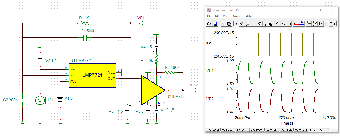
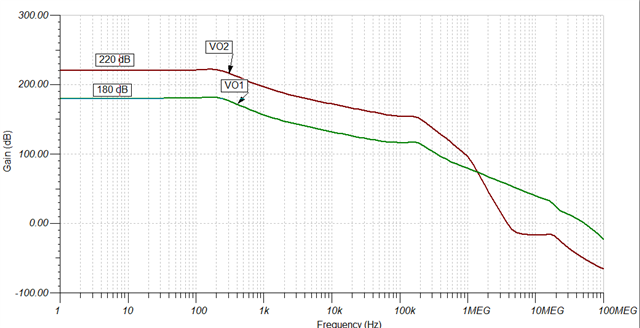
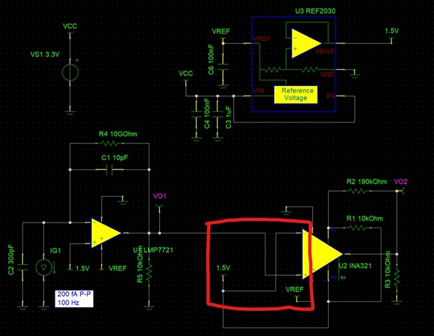
The problem occurred when the input polarity was reversed like below.
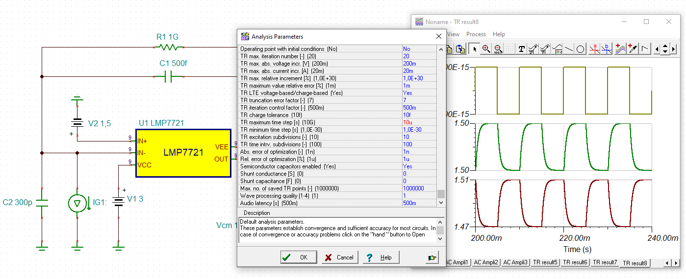
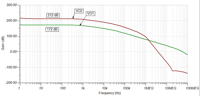
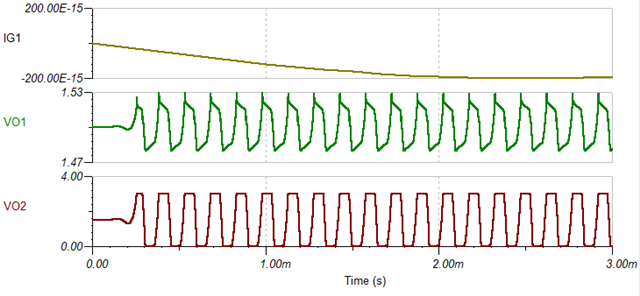
When C1 was 10pF, both circuits worked well during transient simulations.
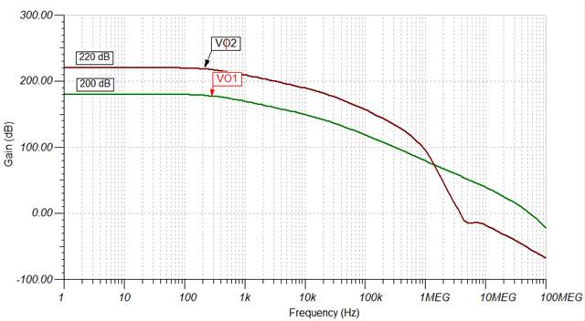
However, C1 was below 3pF, the second circuit started oscillating like below.
The first circuit worked well for the lower capacitance of C1.
Why do the stability problem arise when polarity is reversed?