A related question is a question created from another question. When the related question is created, it will be automatically linked to the original question.
If you have a related question, please click the "Ask a related question" button in the top right corner. The newly created question will be automatically linked to this question.
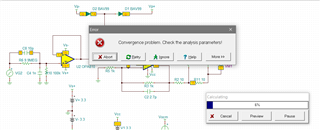
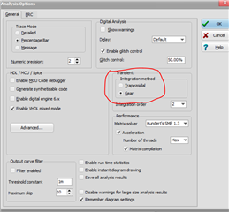
I got it to run, but not very pretty - often, a node like that can use a 10M or so to ground to help the sim,
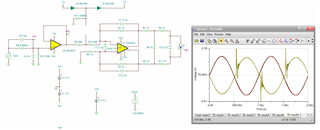
Looks ok up to the input of the FDA,
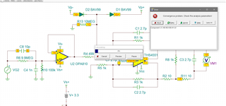
Check DC bias conditions on the THS4551, looked ok, here I slowed it down to 1MHz, still glitching, maybe the diodes are turning on? Try a series 100 that way,
I opened up that line, no change, not sure what is going on here,
Well, you were using the 2016 original model which has some benefits, there is a newer 2020 update where they improved convergence but lost the Zout resonance, it gives better results for me, maybe it will work for you
to be honest, I don't know. Maybe it has to do with your chosen Vocm and supply voltages of THS4551? Or it is just a weird Spice model issue? Eventually, Michael can tell more?
But wasn't the diode clamps at the input of THS4551 originally planned to protect the THS4551 itself? Haven't you said this in an earlier thread? I wouldn't have recommended diode clamps at this location to protect the ADS4222.
Well you need to look at the actual swing in that resistor midpoint clamp - you have a level shift going on for the output Vocm target, This is +/-200V input.
So lets say we want to clamp a little above, just seting those diodes biases to these max swings will clamp diode drop above or below
No, this is not going to work as the impedance changes so much in that clamp point - move you clamp diodes to the OPA810 input.
then add a stage behind the OPA810 and in front of the THS4551 just for the limiting. Mount the protection diodes there and drive them with low impedance.
And, if you are going down that path, don't use diodes, use the OPA698 output clamping amplifier. Operate with some decent max valid swing there, then attenuate in the FDA stage.
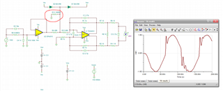
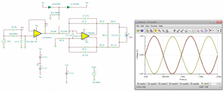
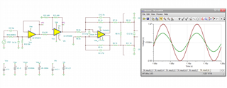
Here is an example using the OPA698, that part requires a lot of output headroom so I went to +/-5V supplies with clamps set to +/-2.1V right now. The input was cut down by 1/2 at the OPA810 input then gain up by 2 in the OPA698 stage. Here is +/-200V input with the expected +/-2V at the OPA698 output, if I increase the input swing from here, that output should start to clip off.
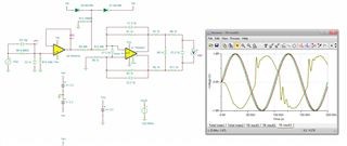
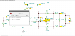
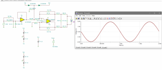
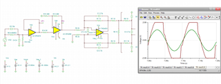
Then, here is +/-250V input,
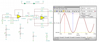
Not as clean as I would have hoped, but when limiting I doubt you care - now this limited output needs to be scaled through the THS4551 correctly - I had cut that gain by 1/2, but then cut it again at the inputs So I may need to go back to a gain of 1, try that next
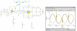
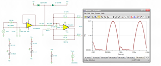
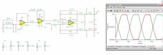
So yes, these are nicely limited outputs single ended at the ADC inputs - not sure if everything is set up right here, but I was just demonstrating how useful the OPA698 migh be in this signal path for hard limiting.